
Magneto-rheological damper

A damper, magnetorheological technology, applied in the direction of shock absorber, shock absorber, spring/shock absorber, etc.

Inactive Publication Date: 2004-12-08
BOSCH REXROTH AG
View PDF2 Cites 22 Cited by
  • Summary
  • Abstract
  • Description
  • Claims
  • Application Information

AI Technical Summary

Problems solved by technology

[0010] A disadvantage of this technical solution is that the entire housing cavity is exposed to the magnetic field and is therefore damped by squeezing the fluid in the piston stroke volume or through the annulus, not as much as by pinching the piston in the fluid

Method used


Image

  • Magneto-rheological damper
  • Magneto-rheological damper
  • Magneto-rheological damper

Examples


Embodiment Construction

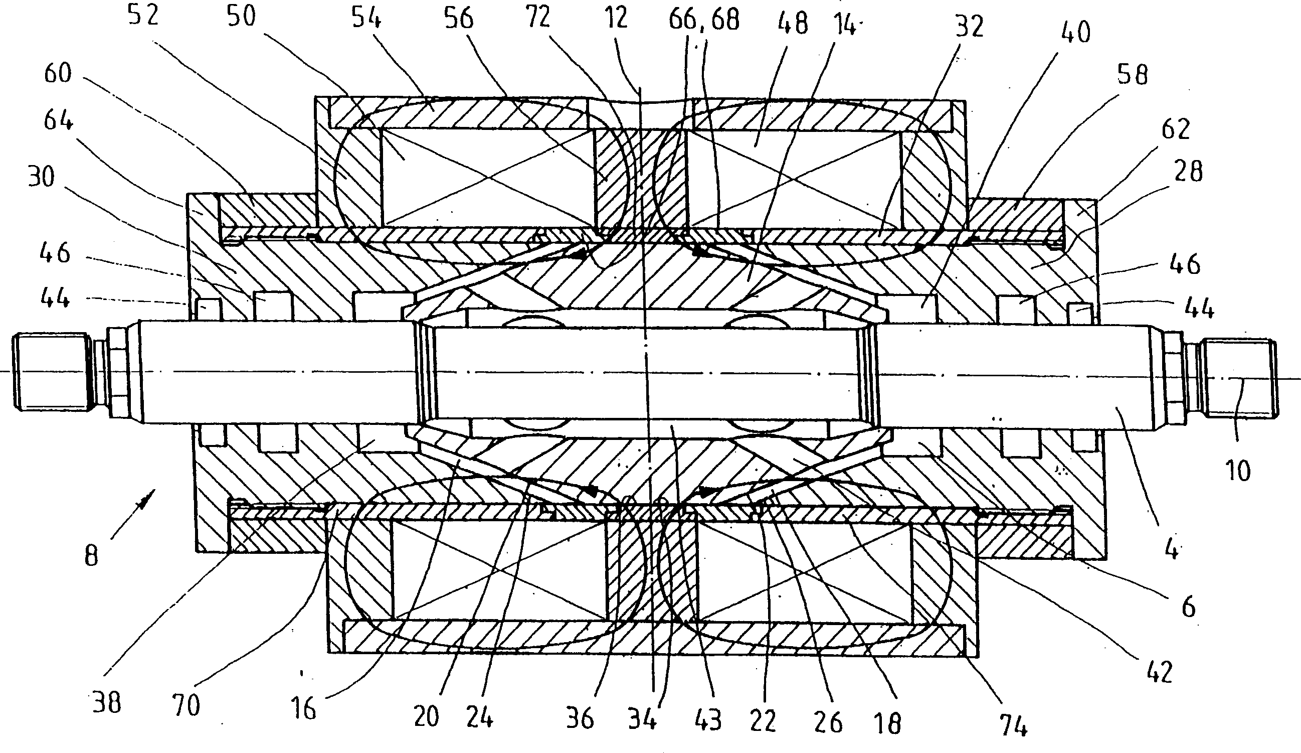
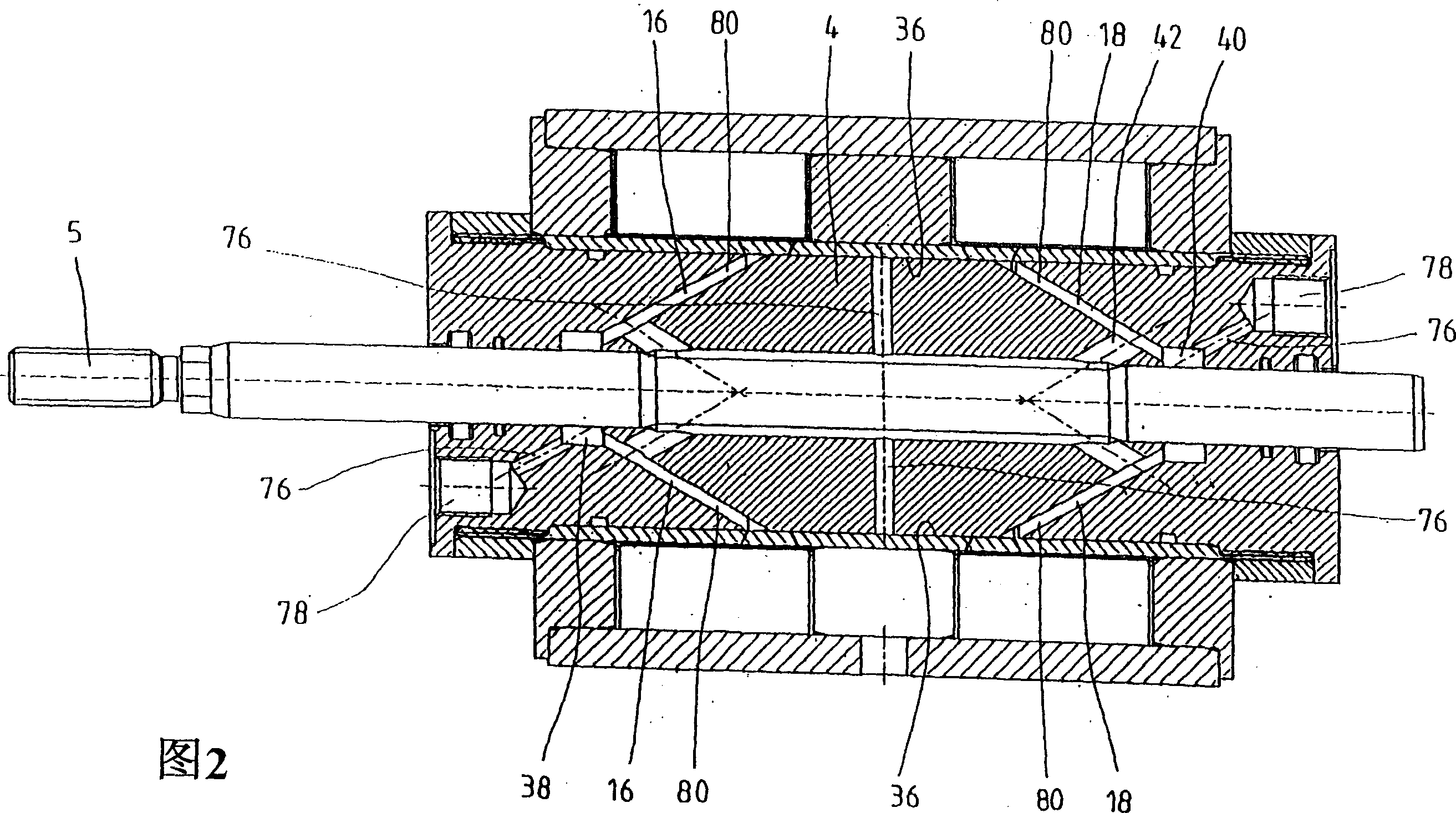
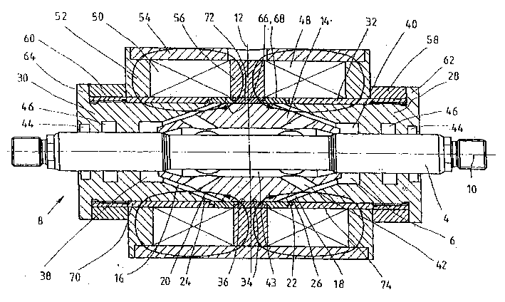
[0024] figure 1 A magneto-rheological (MR) damper 2 according to the invention is shown comprising a piston 4 on a non-magnetic piston rod 5 within a damper chamber 6 of a cylinder 8 filled with magnetorheological fluid Be channeled. The MR damper 2 is designed symmetrically with respect to a transverse axis 12 extending transversely to the longitudinal axis 10 , so that damping strokes are obtained in both axial directions of movement, so that both tensile and compressive forces can be damped.

[0025] The piston 4 , also called the armature, forms two annular spaces 16 , 18 between the inner conical surfaces 20 , 22 and correspondingly shaped outer conical surfaces 24 , 26 of the cylinder 8 , which are inclined to the piston axis 10 . Due to the slanted orientation of the ring spaces 16 , 18 , the volume of the ring spaces is increased compared to the ring spaces in the axial direction, so that correspondingly more fluid can be provided for damping the piston 4 . The inner...


PUM


Abstract

A magneto-rheological (MR) damper is disclosed, comprising a piston running in a cylinder filled with a magneto-rheological fluid, whereby the working volume of which is embodied at an angle to the piston axis between the piston and the cylinder.

Description

technical field [0001] The invention relates to a magneto-rheological (MR) damper in accordance with claim 1 . Background technique [0002] The MR damper comprises a magneto-rheological fluid, a working volume into which the fluid is applied, and an element for generating a magnetic field, wherein the range of mobility of the fluid can be changed by the application of the magnetic field. [0003] The housing cavity is divided by the piston into the piston-swept volume and the cylinder volume, while fluid can flow between the volumes through the openings. Generally, MR dampers operating in valve mode, shear mode or squeeze mode are known. However, individual principles are often mixed together so that no precise classification is possible. [0004] For example in patent specification US5398917 Fig. 3 discloses an MR damper operating in valve mode and shear mode. An opening is formed between the movable piston and the inner wall of the housing. The fluid in the gap is con...

Claims


Application Information

Patent Timeline
Patent Type & Authority Applications(China)
IPC IPC(8): F16F9/32F16F9/34F16F9/53
CPCF16F9/535
Inventor 彼得·马内克贝恩德·温克勒贝恩哈德·曼哈特斯格鲁伯
Owner BOSCH REXROTH AG
Learn More