Measuring method and probe for three-dimensional vector sound intensity

A three-dimensional vector, measurement method technology, applied in the field of measurement probes, can solve the problems of tailing effect, difficult to ensure spatial positioning accuracy, measurement time and spatial positioning accuracy errors are not much improved, etc.

Inactive Publication Date: 2004-12-08
HEFEI UNIV OF TECH
View PDF0 Cites 14 Cited by
  • Summary
  • Abstract
  • Description
  • Claims
  • Application Information

AI Technical Summary

Problems solved by technology

The existing three-dimensional sound intensity vector measurement includes: in the early days, a sound intensity probe was used to measure the three directions of X, Y, and Z respectively. The specific operation needs to be sampled three times. Positioning accuracy, only applicable to steady-state sound field
[0004] Japan's Nittobo Acoustic Instrument Company has developed a MT ver2.0 sound intensity probe rotation device on this basis, and installed B&K4181 and 4178 sound intensity probes on it, and rotated the probe along two tightly combined circular guide rails. It can measure the sound intensity vector in three directions of X, Y and Z; the 50VX model X-Y-Z sound intensity probe produced by Denmark's G.R.A.S. company controls the rotating head through two mechanical push buttons on the handle, so that it turns to three mutually perpendicular direction, so as to measure the sound intensity in three directions respectively; these two measurement methods are more convenient to measure than a single sound intensity probe, but the measurement time and spatial positioning accuracy errors are not much improved.
[0005] In addition, the B&K WA0447 produced by the Danish B&K company and the 50VI-1 three-dimensional vector sound intensity probe produced by the Danish G.R.A.S. company both use three pairs of microphones to sample six channels simultaneously and measure the sound intensity in three directions at a time. However, since the sound pressure at the central point is obtained by averaging the sound pressures measured by six microphones, large errors are introduced, large amplitude fluctuations will appear in the high frequency region, and a certain degree of drag will appear in the time domain. tail effect

Method used


Image

  • Measuring method and probe for three-dimensional vector sound intensity
  • Measuring method and probe for three-dimensional vector sound intensity
  • Measuring method and probe for three-dimensional vector sound intensity

Examples


Embodiment Construction

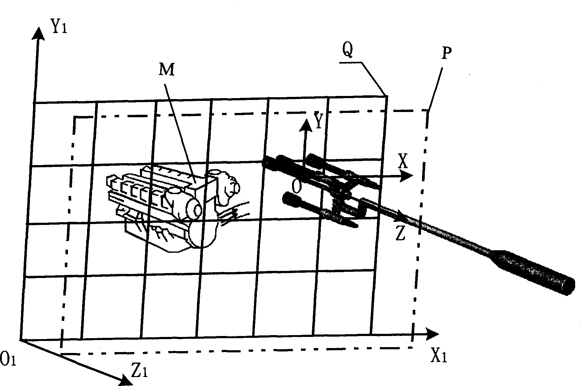
[0067] see figure 1 , Fig. 3, in the present embodiment, measured object M is engine, and its surface to be measured is plane, and concrete measurement process is:

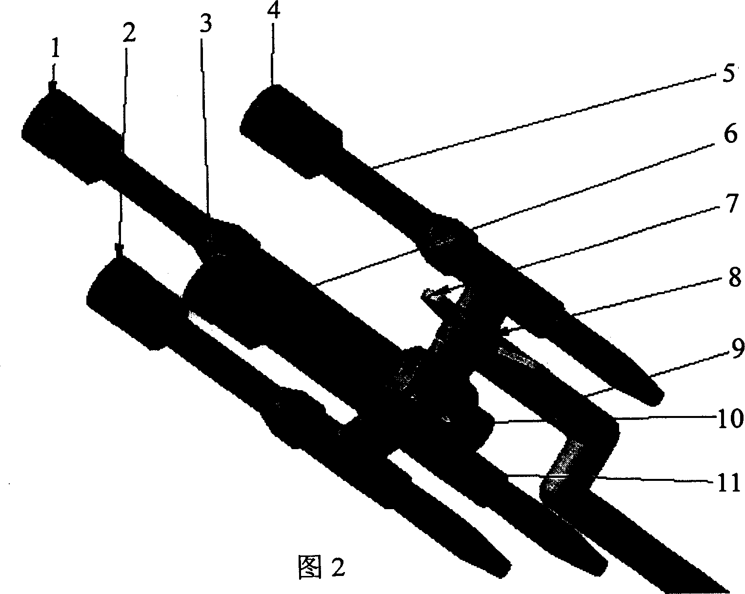
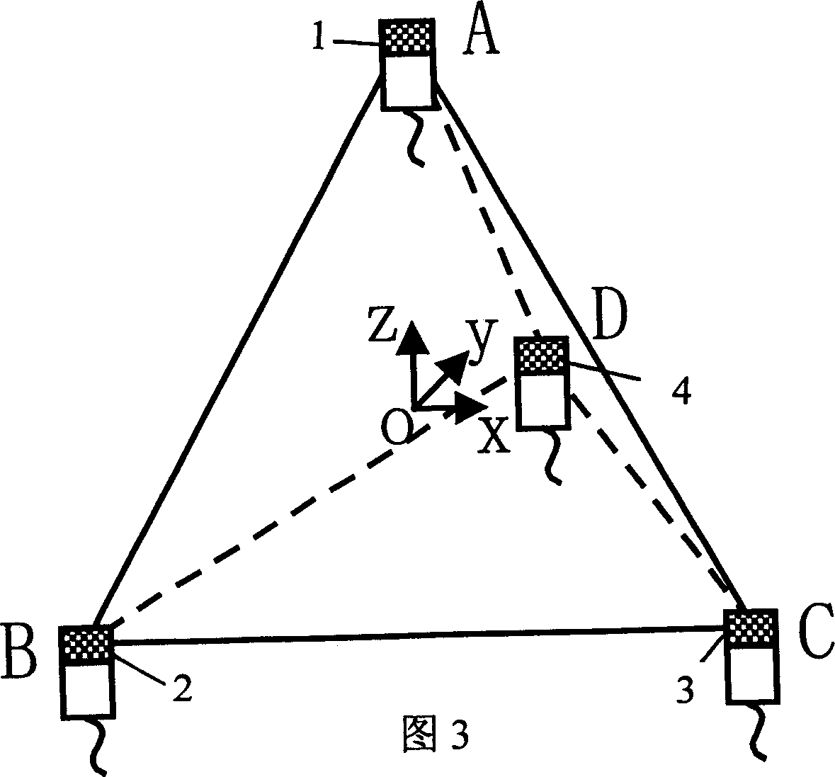
[0068] 1. Construct a geometric coordinate system O 1 -X 1 Y 1 Z 1 Used to determine the measurement positioning grid surface Q{Z 1 =0}; Construct the regular tetrahedron (ABCD) that is used for space vector sound intensity measurement, take the center point (O) of regular tetrahedron as the origin to set up the measurement coordinate system O-XYZ (this measurement coordinate system is a dynamic coordinate system), The vertex (A) on the top of the regular tetrahedron is located on the grid point of the measurement positioning grid surface Q. As the vertex (A) moves on the grid point, the moving track of the center point O (that is, the measurement point) constitutes the measurement Surface P, the distance between the measurement surface P and the measurement positioning grid surface Q is r; the Z-axis directi...


PUM


Abstract

A measuring probe is structured in regular tetrahedron to be carried on for space vector sound indensity meaurement and sound pressure at four top positions is measured so sound iontensity component at six ridges is calculated out according to measurement principle of double sound transmitted having coross-power sound intensity, mathematical model is established between three-dimensional sound intensity at measuring point and sound intensity component for calculating out three-dimensional vector sound intensity. The probe is formed by four sound pressure transducers located on four top positions of regular tetrahedron.

Description

Technical field: [0001] The invention relates to a three-dimensional vector sound intensity measurement technology, more specifically a measurement method and a measurement probe thereof. Background technique: [0002] At present, the commonly used sound intensity measurement method is the double-microphone cross-spectrum sound intensity measurement method. The sound intensity at a certain direction is obtained by measuring the sound pressure at the measuring point through two microphones at a certain distance. [0003] Since the sound intensity is a vector, it can not only determine the size and direction of the sound propagating in space, so the measurement of the three-dimensional vector sound intensity is applied in engineering fields such as noise source positioning, sound source queuing, and spatial acoustic energy flow distribution. Great value. But the key to obtaining the sound intensity vector is to measure the sound intensity components in the X, Y, and Z directi...

Claims


Application Information

Patent Timeline
IPC IPC(8): G01H11/00
Inventor 陈心昭陈剑毕传兴李卫兵
Owner HEFEI UNIV OF TECH
Why Eureka
Try Eureka