


Quick Research
Generate reliable direction feasibility study reports for your R&D in just a few steps.

Technical Q&A
Discover and master advanced knowledge NOW. Basics, ideas, possibilities, all at once.

Find Solutions
As an expert in R&D theories, this can generate solutions to your technical problems instantly.

Evaluate Feasibility
Analyze your overall solution with one click, know your potential R&D risks in advance.

Monitor Landscape
Get weekly tech updates, stay abreast of the latest tech innovations and key insights.
Boosting slurry-supply system for combusting water coal slurry
A coal-water slurry and combustion water technology, applied in the direction of fuel supply, combustion method, combustion equipment, etc., can solve the problems of serious wear of pump wearing parts, short continuous operation time, and influence on continuous operation of boilers, etc.
- Summary
- Abstract
- Description
- Claims
- Application Information
AI Technical Summary
Problems solved by technology
Method used
Image


Examples
Embodiment Construction
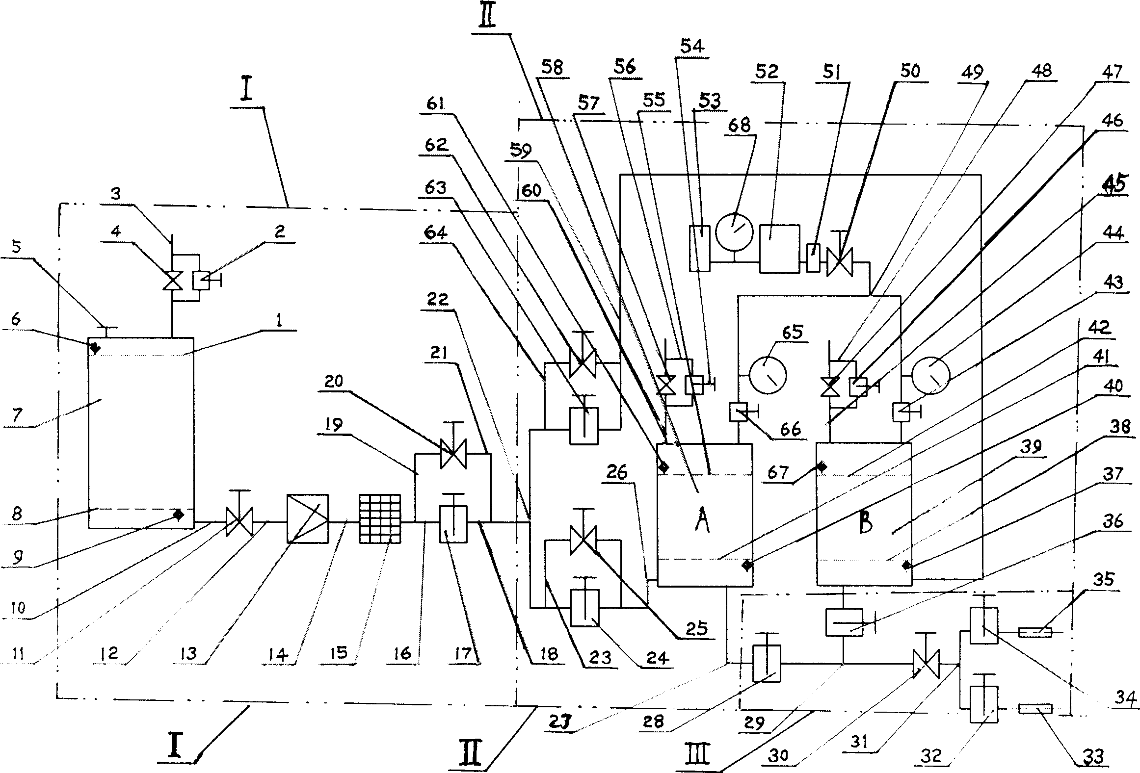
[0009] In the present embodiment, in the coal-water slurry input device (1), comprise the slurry storage tank (7) of storage fuel and fuel delivery pipeline, on the fuel delivery pipeline, there are low-pressure slurry delivery pump (13), filter (15) and The control valve on the pipeline and the delivery of the coal-water slurry are replaced by the low-pressure slurry delivery pump (13) by the original high-pressure slurry supply pump. This fuel delivery pipe is connected with A pressurized slurry supply tank (58). In the pressurized slurry supply device (II), two pressurized slurry supply tanks (39, 58) of A and B have been adopted, and the two pressurized slurry supply tanks are connected with the compressed air source, and two pressurized slurry storage tanks ( 58, 39) switch between each other through the control of the central control cabinet to deliver high-pressure coal-water slurry to the coal-water slurry spray guns (33, 35) in turn. A booster slurry supply tank fuel...
PUM
 Abstract
Description
Claims
Application Information
 - R&D Engineer
- R&D Manager
- IP Professional
- Industry Leading Data Capabilities
- Powerful AI technology
- Patent DNA Extraction
Browse by: Latest US Patents, China's latest patents, Technical Efficacy Thesaurus, Application Domain, Technology Topic, Popular Technical Reports.
© 2024 PatSnap. All rights reserved.Legal|Privacy policy|Modern Slavery Act Transparency Statement|Sitemap|About US| Contact US: help@patsnap.com