System for repolarizing transducers in an ultrasonic probe
A technology of ultrasound and transducers, applied in the field of ultrasound probes and ultrasound imaging equipment, can solve a lot of work and other problems
- Summary
- Abstract
- Description
- Claims
- Application Information
AI Technical Summary
Problems solved by technology
Method used
Image

Examples
no. 1 example
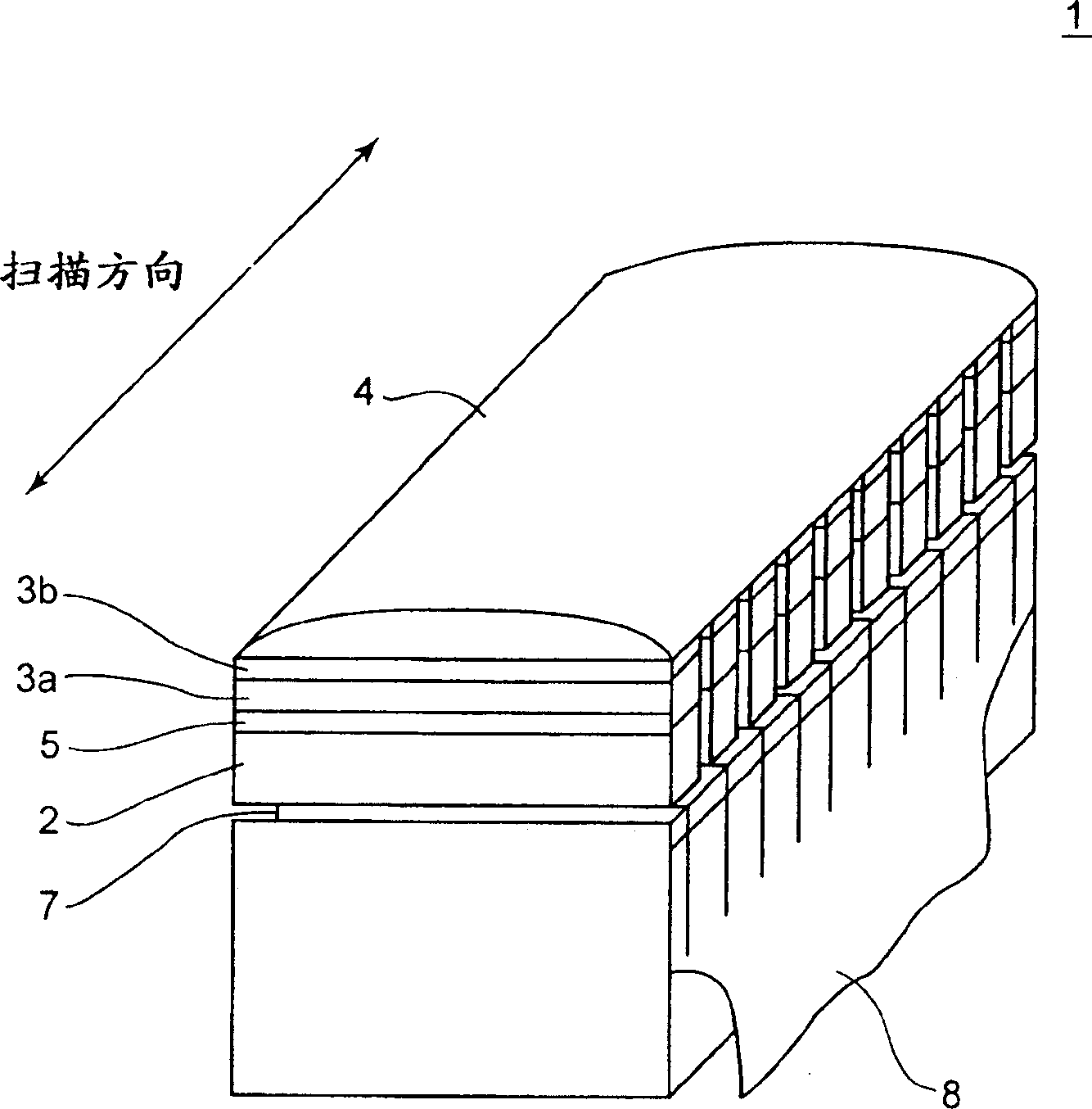
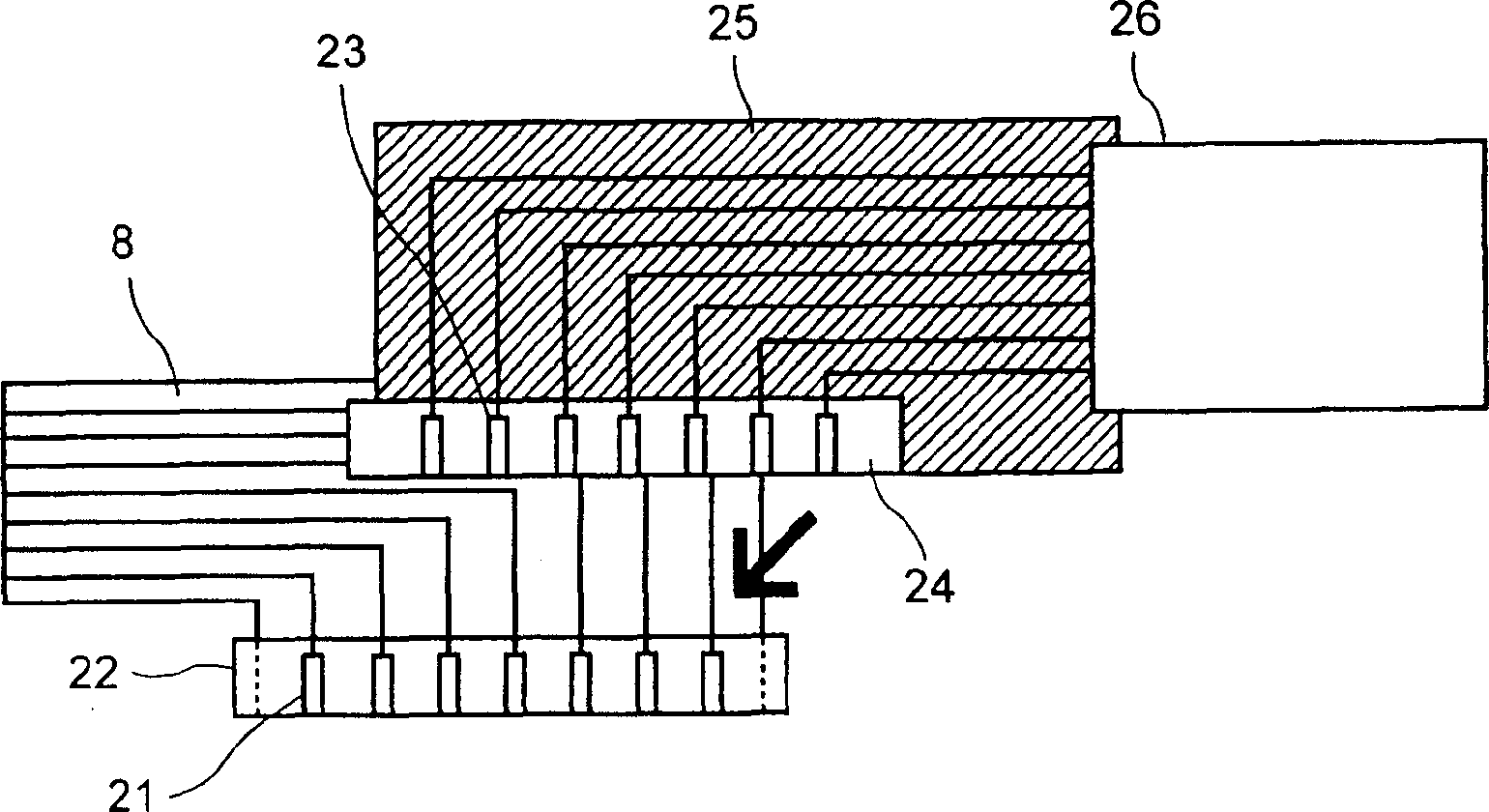
[0041] Figure 5 is a first exemplary structural block diagram of the repolarization system according to the first embodiment of the present invention. Such as Figure 5 As shown, the repolarization system includes an ultrasonic probe repolarization device 50 and an ultrasonic probe 1 . The ultrasonic probe repolarization device 50 includes a connector 51 , a connection line 52 , a switch unit 53 , a high voltage power supply 54 , a controller 55 and an input unit 56 . The connector 51 is detachably connected to the connector 57 of the ultrasound probe 1 . The connector 57 is connected to the cable 26 . Other structures of the ultrasonic probe 1 are similar to those described above. Therefore, description of the ultrasonic probe 1 is omitted here.
[0042] The switching unit 53 includes a plurality of switching elements. The switching element is turned on / off by the controller 55 . At least a part of the switching element corresponds to the land 21 (23). Any switching ...
no. 2 example
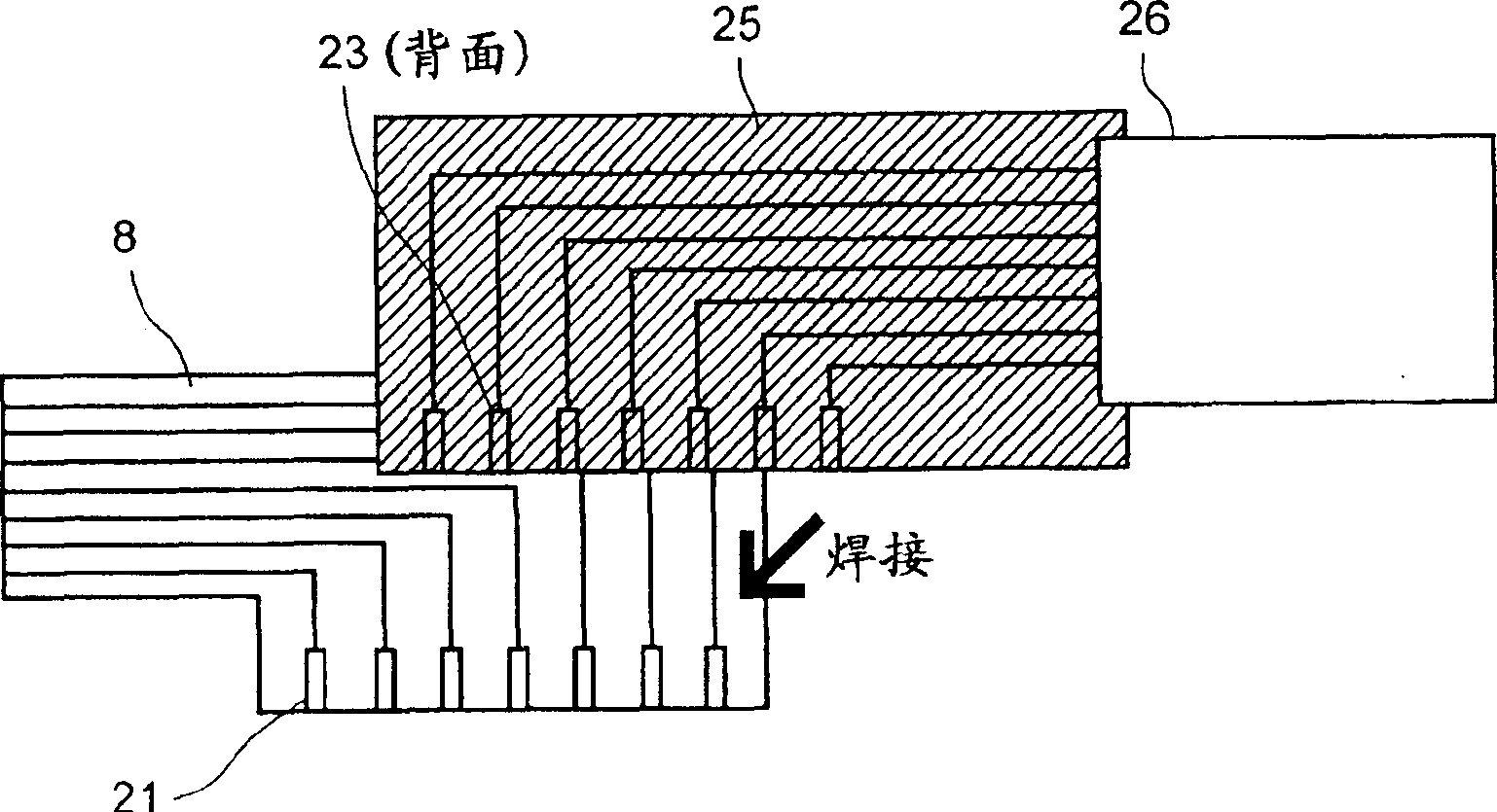
[0049] Figure 6 is a block diagram of the second exemplary structure of the repolarization system according to the second embodiment of the present invention. exist Figure 6 in, give with figure 1 , 2A Components with the same number as shown in 5 will work in a similar manner. Therefore, detailed descriptions of these components will be omitted here.
[0050] In the repolarization system according to the second embodiment, an ultrasound probe repolarization apparatus 60 includes a controller 61 instead of the controller 55 , an ultrasound probe identification table memory 62 , and an input unit 63 instead of the input unit 56 . The controller 61 controls the switching unit 53 and specifies which switching elements are to be turned on (or which lands are to be supplied with a predetermined high voltage). The controller 61 also controls the switching unit 53 to be turned on during the on period of the switching element. In addition, the controller 61 also controls the h...
no. 3 example
[0058] When it is possible to classify the various types of ultrasonic probes 1 into a smaller number of groups according to the supply voltage required for repolarization, these classified voltage types can be input to the controller of the ultrasonic probe repolarization device to control the repolarization change. This classification is based on the fact that certain types of ultrasound probes can be repolarized with similar voltages. Applying control based on this supply voltage can simplify the operation of the operator and the control of the ultrasound probe repolarization device. A supply voltage corresponds to a predetermined voltage to be supplied for repolarization.
[0059] Figure 7 is a block diagram of a third exemplary structure of a repolarization system according to a third embodiment of the present invention. exist Figure 7 in, give with figure 1 , 2AComponents with the same number as shown in 5 will work in a similar manner. Therefore, detailed descr...
PUM
 Abstract
Description
Claims
Application Information
 - R&D
- Intellectual Property
- Life Sciences
- Materials
- Tech Scout
- Unparalleled Data Quality
- Higher Quality Content
- 60% Fewer Hallucinations
Browse by: Latest US Patents, China's latest patents, Technical Efficacy Thesaurus, Application Domain, Technology Topic, Popular Technical Reports.
© 2025 PatSnap. All rights reserved.Legal|Privacy policy|Modern Slavery Act Transparency Statement|Sitemap|About US| Contact US: help@patsnap.com