
Transparent material photoelectric display device

A transparent material, photoelectric display technology, applied in display devices, illuminated signs, instruments, etc., can solve the problems of unsatisfactory display effect, long conduction distance, complicated manufacturing process, etc., and achieve great advantages and promotion value, The effect of low technical requirements and simple structure

Inactive Publication Date: 2004-11-17
SHANGHAI INST OF OPTICS & FINE MECHANICS CHINESE ACAD OF SCI
View PDF0 Cites 5 Cited by
  • Summary
  • Abstract
  • Description
  • Claims
  • Application Information

AI Technical Summary

Problems solved by technology

For side-emitting optical fiber, due to the refraction of light during transmission, attenuation will occur, and uneven brightness will be caused when the transmission distance is too long
Fiber optic lighting is relatively dark, suitable for use in places where the ambient brightness is not too high, otherwise the display effect is not ideal
Whether it is a neon light or an optical fiber lighting system, when it is made into a display screen, it must be inlaid or installed on the graphic surface that needs to be illuminated. The manufacturing process is relatively complicated, the cost is high, and it affects the visual effect during the day.

Method used


Image

  • Transparent material photoelectric display device
  • Transparent material photoelectric display device
  • Transparent material photoelectric display device

Examples


Embodiment Construction

[0022] Below in conjunction with embodiment and accompanying drawing, invention is described further in detail:

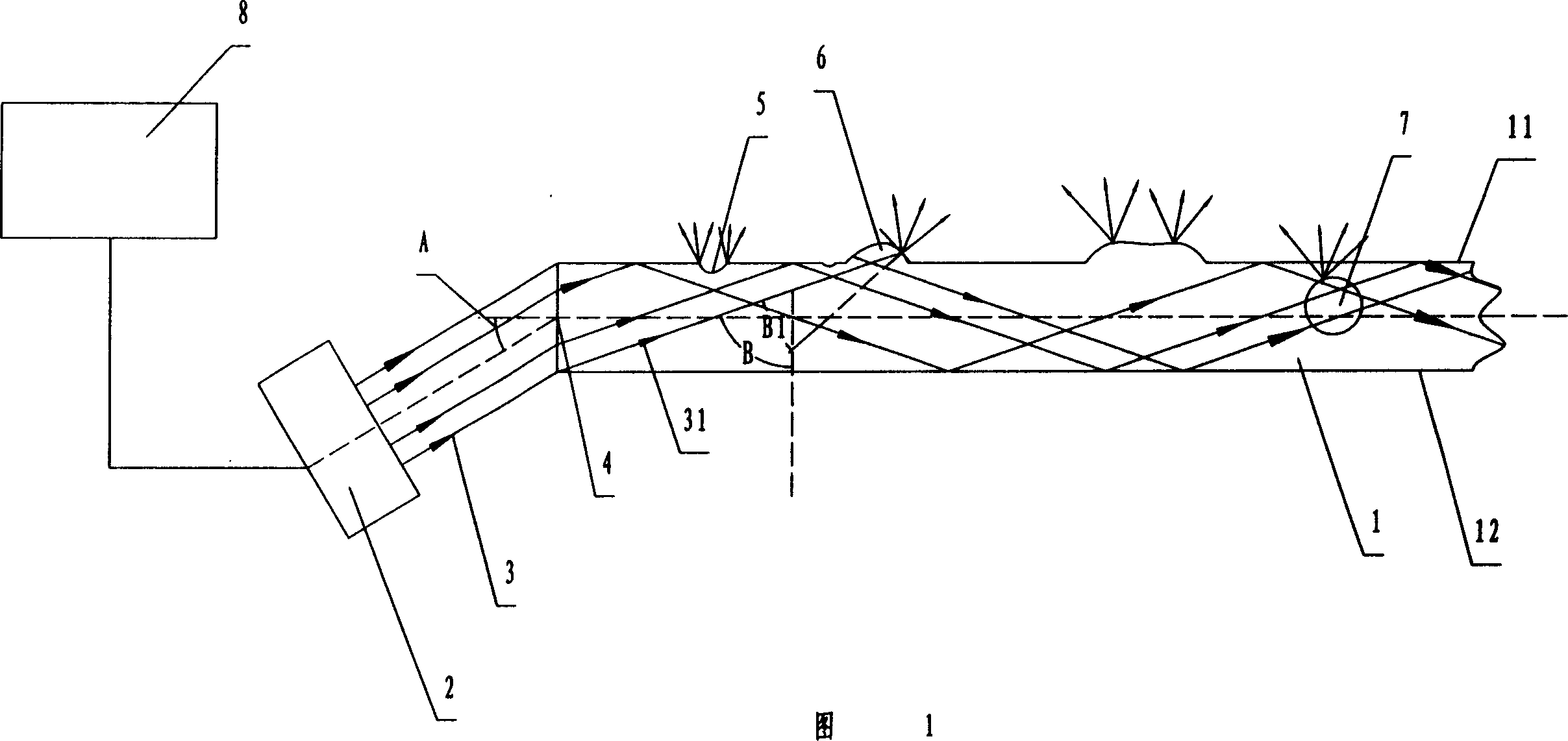
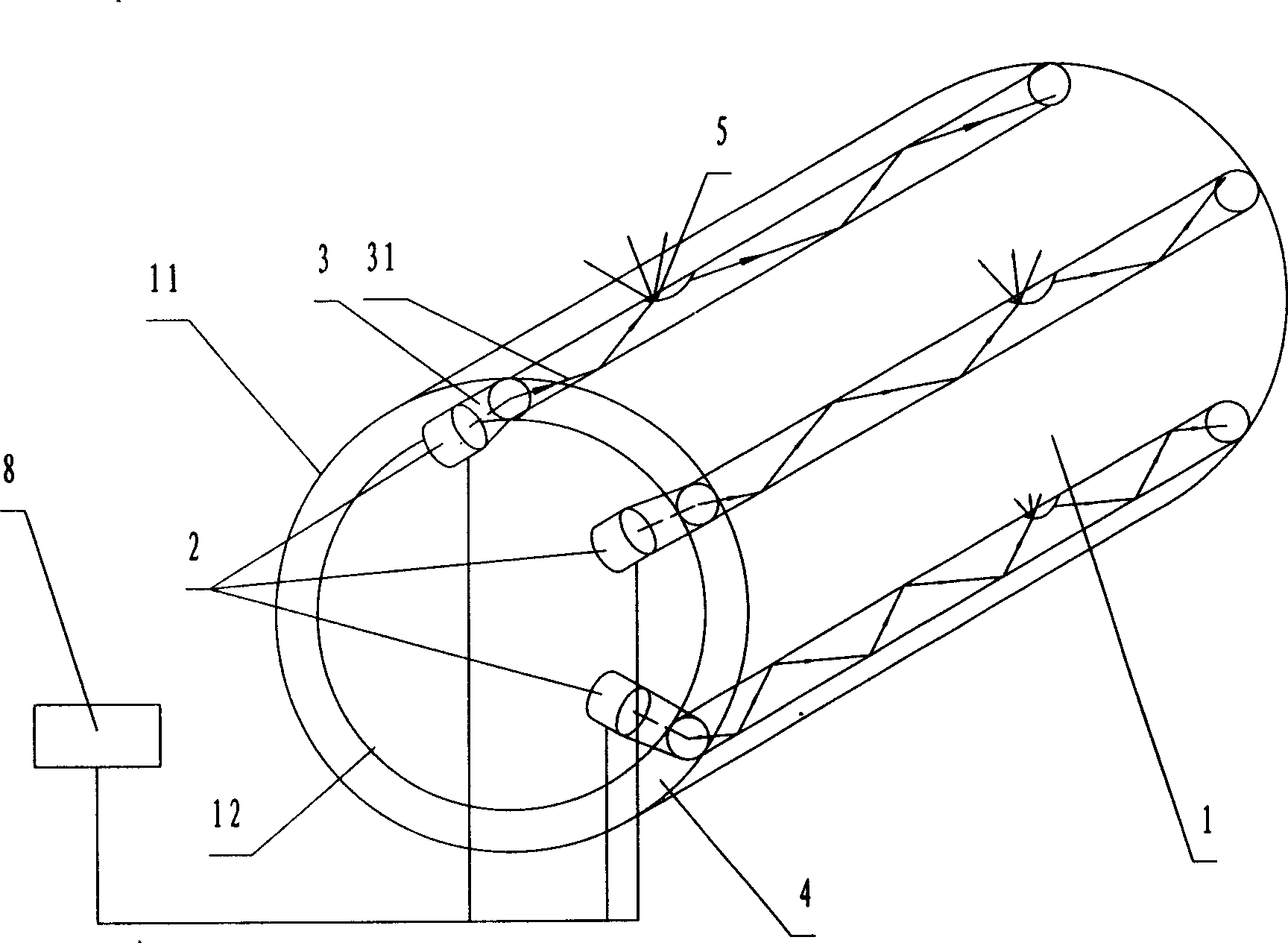
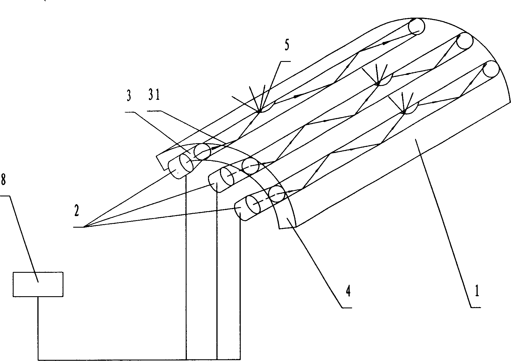
[0023] Please refer to FIG. 1 . FIG. 1 is a schematic diagram of the structure and basic working principle of Embodiment 1 of a transparent material optoelectronic display device of the present invention. As can be seen from the figure, the transparent material photoelectric display device of the present invention is characterized in that it includes a transparent material photoelectric display screen 1, a radiation source 2, a fixing device (not shown in the figure) of the radiation light source, and the basic structure of the photoelectric display screen 1 is It is a transparent parallel plate with transparent or translucent concave 5 and convex 6 patterns or characters on its surface or inside, and the radiation light source 2 is encapsulated in a transparent material photoelectric display by its fixing device (not shown in the figure). On the cross-sectional ed...


PUM


Abstract

The invention is a kind of transparent material photoelectric displaying device. The character lies in: it includes the transparent material photoelectric displaying screen, the radiation light source, and the fixing device for the light source. The base structure of the screen is a transparent parallel board; it also can be the transparent pipe structure or transparent arc structure, there has the transparent or semitransparent concave, convex pattern or word on its surface or in the screen, the radiation light source is fixed on edge of the cross section of the screen through the fixing device. The beam of the light source enters the screen from the cross section edge with angle greater than or equal to the critical angle of the transparent material. The structure is simple; the quantity of the elements is little. The cost is low.

Description

Technical field: [0001] The invention relates to a photoelectric display screen, in particular to a transparent material photoelectric display device. It is mainly used in the manufacture of indoor and outdoor advertising luminous display screens. Such as indoor nameplates, billboards, signs, outdoor road signs, billboards, nameplates of companies and other units, static or dynamic luminous display of facades and window advertisements of shopping malls, hotels, etc., etc. Background technique: [0002] There are many traditional decorative lighting methods for indoor and outdoor advertising, such as neon lights and fiber optic lighting systems. The characteristics of neon lights are: they can be made into any shape and display a variety of colors, and the length of the lamp tube can also be precisely controlled. However, neon lamps must work under high voltage (about 9-12kv), so electrical safety must be paid attention to when using them, and their manufacturing process is...

Claims


Application Information

Patent Timeline
Patent Type & Authority Applications(China)
IPC IPC(8): G09F13/00
Inventor 王宪涛林强谭建中刘志刚桑娜王利朱健强
Owner SHANGHAI INST OF OPTICS & FINE MECHANICS CHINESE ACAD OF SCI
Learn More