
Network monitoring management system

A network monitoring and management system technology, applied in the field of computer network management application software, can solve problems such as failure to be solved in time, waste of human resources, lack of database management, etc., to ensure efficient and effective operation, ensure smooth operation, and facilitate system configuration. Effect

Inactive Publication Date: 2004-11-17
NEUSOFT CORP
View PDF0 Cites 51 Cited by
  • Summary
  • Abstract
  • Description
  • Claims
  • Application Information

AI Technical Summary

Problems solved by technology

[0002] At present, the existing network management application software generally refers to the definition of equipment: hardware entities such as hosts and network devices, but lacks effective management of key application software running on hosts, such as databases and application programs. The method is relatively simple, usually through the sound alarm, and relevant maintenance personnel are required to be on duty on site, resulting in waste of human resources. If there is no on-site personnel on duty, the maintenance personnel cannot be notified in time, which will inevitably cause failures that cannot be resolved in time, and cause harm to the enterprise and users. Economic loss, on the other hand, ordinary network management software will generally send query status requests to network devices continuously. If the system is busy, it will inevitably occupy valuable system resources and affect system operation. Furthermore, ordinary network management software implements 7× 24-hour monitoring, which will cause false alarms for those devices that do not operate 7×24 hours
In addition, ordinary network management software generally cannot realize the monitoring and management of popular database software systems on the market, and cannot handle various database management failures in a timely manner, and the usual network management software is only centralized management. Once the network management monitoring system fails, it will not be able to The network is monitored and managed, which brings inconvenience to the normal operation of the network

Method used

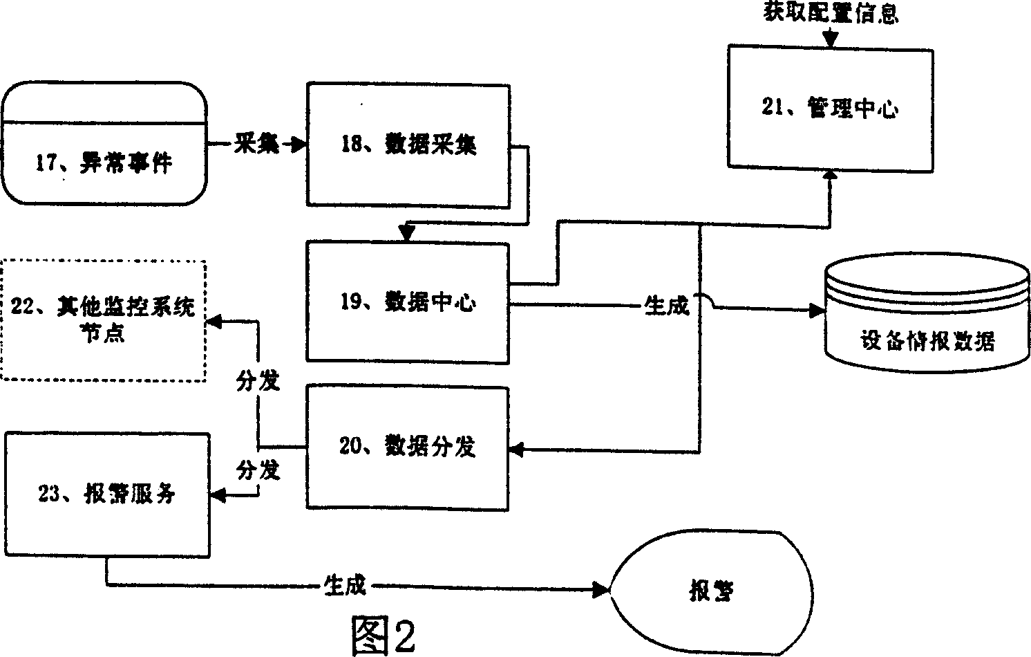

Image

  • Network monitoring management system
  • Network monitoring management system
  • Network monitoring management system

Examples


Embodiment Construction

[0070] Below in conjunction with accompanying drawing and embodiment the network management monitoring system of the present invention is further described:

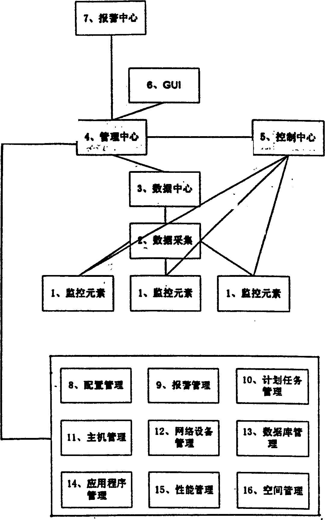
[0071] The realization principle is as figure 1 Shown:

[0072] The monitoring system is composed of at least one monitoring element 1, data collection 2, data center 3, management center 4, control center 5, GUI user interface 6, alarm center 7 and other parts.

[0073] The management center 4 is composed of configuration management 8, alarm management 9, planned task management 10, host management 11, network device management 12, database management 13, application program management 14, performance management 15, space management 16 and other components.

[0074] The implementation method consists of the following steps:

[0075] Equipment configuration: First, monitor elements such as hosts, network devices, and databases are automatically discovered through the configuration management system, and users can furth...


PUM


Abstract

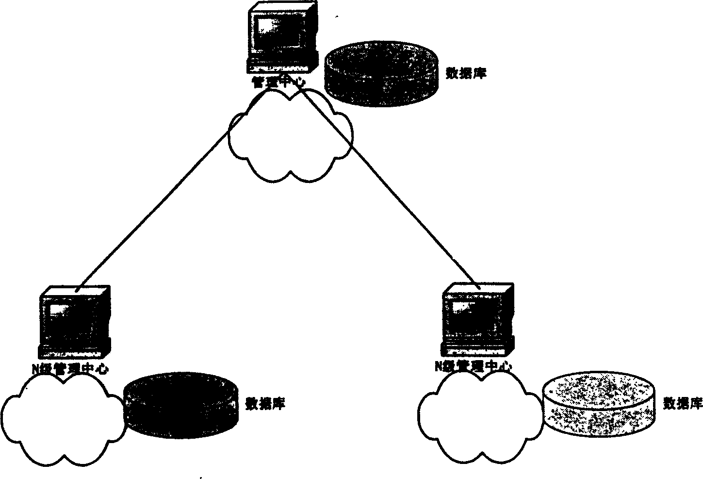
The invention is a kind of computer network software, which is a new multi-function network supervising management method. The host computer, network device, databank, and application procedure are defined as supervising element according to different particle size, the different domain supervising elements are allocated to different network supervising management joint, and the centre realizes grade management through center supervising. The states of the network device, databank and application system can be informed to the field network maintaining person and remote network maintaining person, at the same time, it can manages many kinds of databank, and application system. The states of the network devices can be sent to relative maintaining person with acousto-optic alarming, voice music alarming, message alarming, telephone alarming, Email alarming, messenger alarming. It can realize the supervising and management to many kinds of databank and application systems.

Description

Technical field [0001] The invention relates to a computer network management application software, which mainly realizes the monitoring, management and alarm functions of the operation status of the host computer, network equipment, database, application software system and the like. Background technique [0002] At present, the existing network management application software generally refers to the definition of equipment: hardware entities such as hosts and network devices, but lacks effective management of key application software running on hosts, such as databases and application programs. The method is relatively simple, usually through the sound alarm, and relevant maintenance personnel are required to be on duty on site, resulting in waste of human resources. If there is no on-site personnel on duty, the maintenance personnel cannot be notified in time, which will inevitably cause failures that cannot be resolved in time, and cause harm to the enterprise and users. ...

Claims


Application Information

Patent Timeline
IPC IPC(8): G06F9/44G06F11/30
Inventor 侯俊王乔东计进波侯家欣于伟超凌云毅
Owner NEUSOFT CORP
Learn More