
Display device, electronic machine and diplsy device mfg. method

A technology of display device and manufacturing method, applied in semiconductor/solid-state device manufacturing, identification device, lighting device, etc.

Inactive Publication Date: 2004-10-06
SEIKO EPSON CORP
View PDF2 Cites 12 Cited by
  • Summary
  • Abstract
  • Description
  • Claims
  • Application Information

AI Technical Summary

Problems solved by technology

Therefore, on the production equipment side, although it is necessary to control the discharge position and the discharge amount of the functional liquid with higher precision, there is also a balance with the above-mentioned problem of increasing the size of the substrate, which has become a major problem.

Method used


Image

  • Display device, electronic machine and diplsy device mfg. method
  • Display device, electronic machine and diplsy device mfg. method
  • Display device, electronic machine and diplsy device mfg. method

Examples


Embodiment Construction

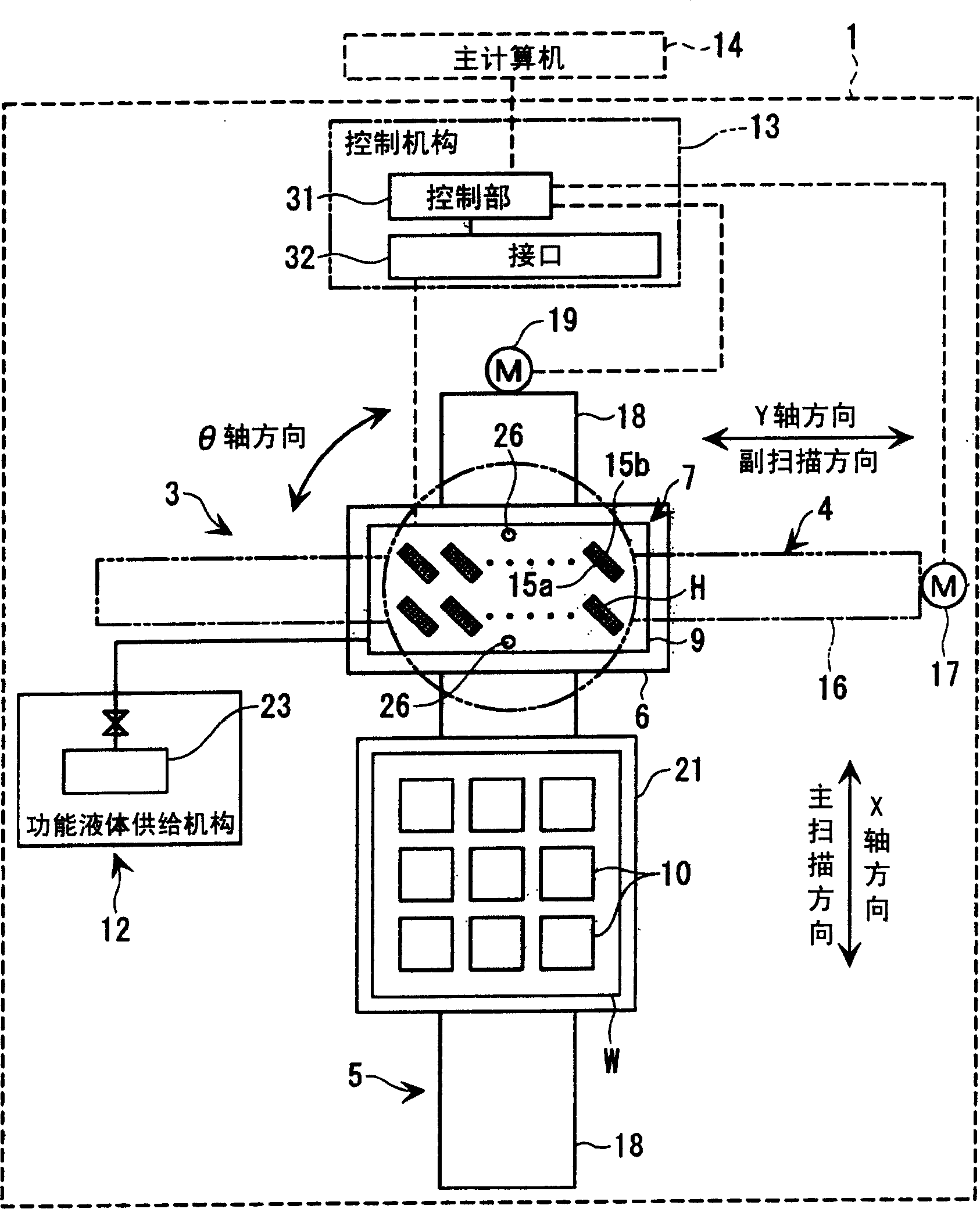
[0069] Hereinafter, a display device, an electronic device, and a method of manufacturing the display device according to the present invention will be described with reference to the drawings. Since the ejection head (functional liquid droplet ejection head) of an inkjet printer (functional liquid droplet ejection device) can eject tiny ink droplets (functional liquid droplets) in dots with excellent precision, it is expected that, for example, by It can be applied to the manufacturing field of various parts by using special ink or luminescent or photosensitive resin in the object liquid). In this embodiment, for example, in a method of manufacturing a so-called flat-panel display such as an organic EL display device or a liquid crystal display device, the filter material is ejected from the functional droplet ejection head of the functional droplet ejection device (ink jet method) or functional liquids such as luminescent materials, to form the EL light-emitting layer and ho...


PUM


Abstract

To provide a display device, an electronic apparatus, and a method of manufacturing the display device, which are capable of preventing growth in size of a production line and the resultant increase in cost without deteriorating display quality, by using an elongate or contractile substrate, there is provided a display device in which an element layer having electrodes and a photo-functional layer is formed on a substrate, the substrate is made of an irreversible elongate material, and the element layer is made of an elastic material and provides an adhesive property to the substrate.

Description

technical field [0001] The present invention relates to a display device, an electronic device, and a method for manufacturing a display device in which an element layer having an electrode and an optical function layer is formed on a substrate. Background technique [0002] Conventionally, people have known a color display device in which a light-emitting layer and a hole injection layer of each pixel are formed by using an inkjet method of ejecting a functional liquid such as a light-emitting material to form a pattern of the light-emitting material. The material is an organic EL (Electro-Luminescence) display device using an organic light-emitting material (for example, refer to Patent Document 1). [0003] (Patent Document 1) [0004] Japanese Patent Application Publication No. 10-12377 [0005] In such an organic EL display device, element layers (switching elements, electrodes, hole injection / transport layers, light emitting layers, etc.) are formed on a substrate of...

Claims


Application Information

Patent Timeline
Patent Type & Authority Applications(China)
IPC IPC(8): H05B33/02G02F1/1333G02F1/167G09F9/30H05B33/04H05B33/06H05B33/10H05B33/22H10K99/00
CPCG02F1/167H01L51/5253H01L51/56H01L27/3244G02F1/1333G02F2001/133302H01L51/0005H01L51/52G02F1/133305Y02E10/50H01L27/3246H01L51/0097Y02E10/549Y02P70/50G02F1/133302H10K59/122H10K71/135H10K77/111H10K59/873B43K27/08B43K23/06H10K50/80H10K59/12H10K71/00H10K50/844
Inventor 三浦弘纲
Owner SEIKO EPSON CORP
Learn More