
Liquid-crystal displaying board driving method, circuit and liquid-crystal displaying board

A technology of a liquid crystal display panel and a driving method, which is applied to static indicators, instruments, etc., can solve the problems of grayscale influence of display unit and influence of LCD display effect, etc.

Inactive Publication Date: 2004-09-22
TPO DISPLAY
View PDF0 Cites 0 Cited by
  • Summary
  • Abstract
  • Description
  • Claims
  • Application Information

AI Technical Summary

Problems solved by technology

In the case that the common electrode voltage VCOM cannot be kept constant, the gray scale displayed by the display unit will be affected, which will affect the display effect of the LCD.

Method used


Image

  • Liquid-crystal displaying board driving method, circuit and liquid-crystal displaying board
  • Liquid-crystal displaying board driving method, circuit and liquid-crystal displaying board
  • Liquid-crystal displaying board driving method, circuit and liquid-crystal displaying board

Examples


Embodiment

[0035] Figure 4 A schematic diagram of an equivalent circuit of a thin film transistor liquid crystal display panel and its peripheral driving circuit according to an embodiment of the present invention. As shown in the figure, the LCD panel 4 is formed by criss-crossing data electrodes (indicated by D1, D2, D3, ... Dm) and gate electrodes (indicated by G1, G2, ... Gn), and each group is staggered The data electrode and gate electrode can be used to control a display unit (display unit), for example, the data electrode D1 and the gate electrode G1 can be used to control the display unit 400, and the data electrode D2 and the gate electrode G1 can be used to control the display unit. 401. The display units 400 - 402 form a display unit group 420 , the display units 403 - 405 form a display unit group 422 , the display units 410 - 412 form a display unit group 426 , and the display units 413 - 415 form a display unit group 428 . For the convenience of explanation, Figure 4 ...


PUM


Abstract

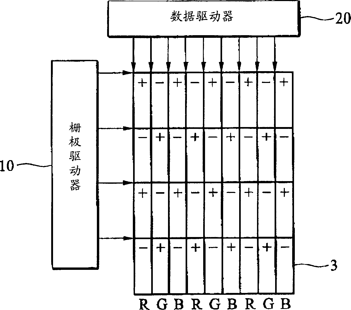
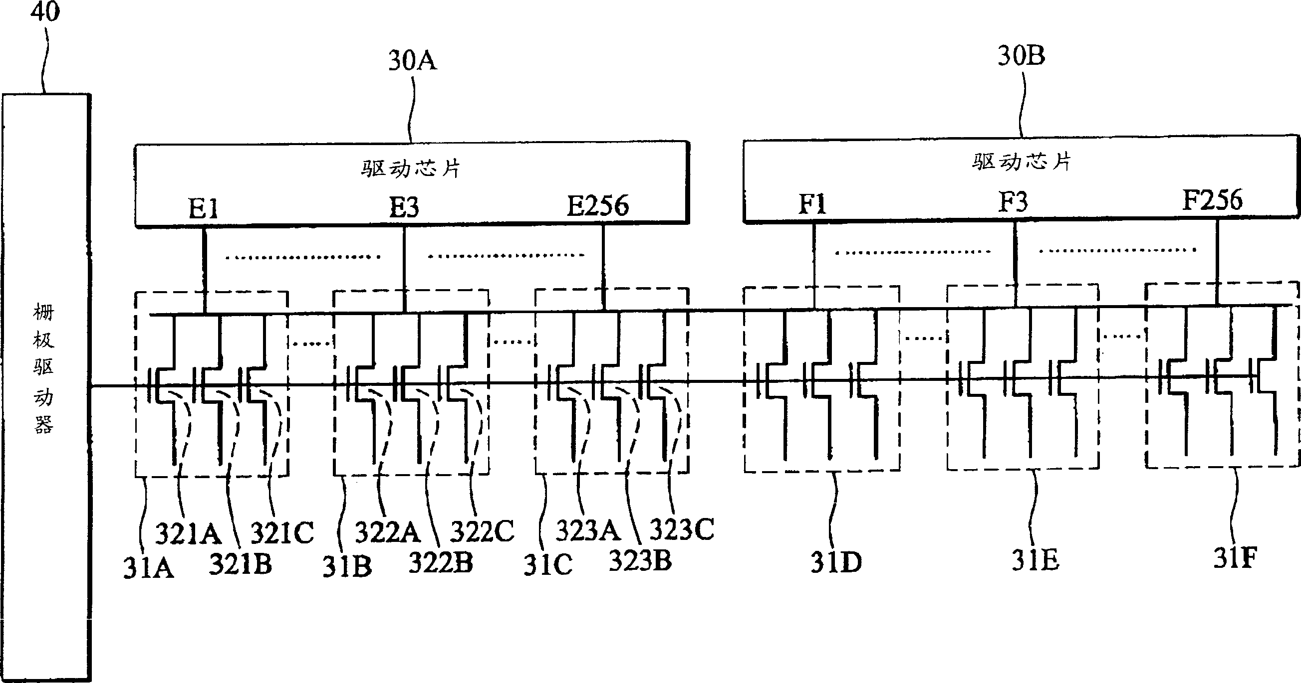
A method for driving a liquid crystal display panel is suitable to such liquid crystal display panel that it comprises a driving chip and a plurality of displaying unit groups having a plurality of displaying units which are connected to corresponding gate electrodes and data electrodes respectively; said driving chip drives the individual displaying units of respective displaying unit groups simultaneously. The method comprises the following steps: firstly, providing a plurality of video signals to the displaying unit groups to drive the individual displaying units, wherein the individual displaying units of the adjacent displaying unit groups receive the video signals with contrary polarities, and finally, providing the scanning signals to the gate electrodes.

Description

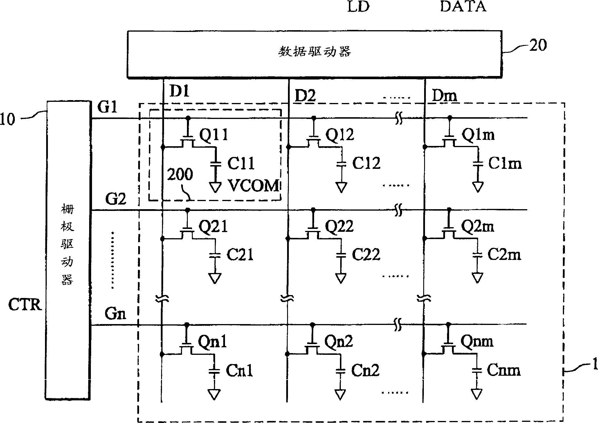
technical field [0001] The present invention relates to a liquid crystal display panel drive circuit and a liquid crystal display panel, in particular to a data driving method for a liquid crystal display panel that simultaneously drives its respective corresponding display units with multiple output channels of a drive chip, and proposes a A liquid crystal display panel driving circuit capable of eliminating cross-talk and a method for improving picture quality by using the driving circuit. Background technique [0002] figure 1 A schematic diagram showing an equivalent circuit of a known thin film transistor liquid crystal display panel (liquid crystal display panel, hereinafter referred to as LCD panel) and its peripheral driving circuit. As shown in the figure, the LCD panel 1 is formed by criss-crossing data electrodes (indicated by D1, D2, D3, ... Dm) and gate electrodes (indicated by G1, G2, ... Gn). Each set of interleaved data electrodes and gate electrodes can be...

Claims


Application Information

Patent Timeline
IPC IPC(8): G09G3/36
Inventor 王清桐
Owner TPO DISPLAY
Learn More