Phased array probe for scanning imager

A phased array probe and scanning imaging technology, applied in the field of phased array probes, can solve problems such as limitations, low efficiency, and the inability of the probe to directly emit shear waves, and achieve the effect of avoiding energy loss or other interference and avoiding impact

Inactive Publication Date: 2004-09-22
INST OF ACOUSTICS CHINESE ACAD OF SCI
View PDF0 Cites 10 Cited by
  • Summary
  • Abstract
  • Description
  • Claims
  • Application Information

AI Technical Summary

Problems solved by technology

[0005] The purpose of the present invention is to overcome the shortcomings of the scanning imaging device in the prior art that the probe cannot directly emit shear waves, thus having low ef

Method used


Image

  • Phased array probe for scanning imager
  • Phased array probe for scanning imager
  • Phased array probe for scanning imager

Examples


Embodiment Construction

[0019] Below in conjunction with accompanying drawing and specific embodiment the present invention is described in further detail:

[0020] like figure 1 As shown, 8 transducer units 2 are spaced in parallel along the width direction to form a linear array, and the distance between adjacent transducer units 2 is 0.1 mm; this array is embedded in the support structure 1, and the support structure is epoxy Resin material.

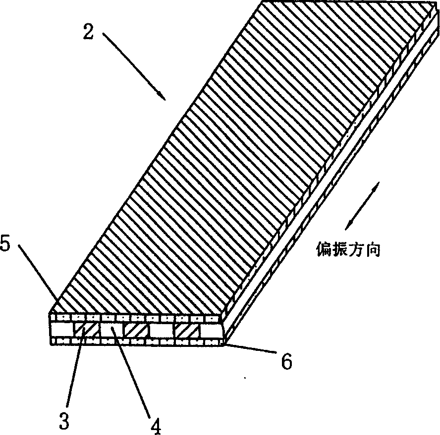
[0021] The structure of the transducer unit 2 is as figure 2 As shown, it is substantially cuboid, and its width is 0.8 millimeters, and thickness is 1.1 millimeters, and length is 10 millimeters, and the wavelength of this transducer unit 2 emitting sound waves is 3 millimeters (corresponding to the situation that detection body is metallic steel), In its width direction, there are 3 strip-shaped piezoelectric blocks 3 and 4 non-piezoelectric blocks 4 alternately placed; the polarization direction of the piezoelectric blocks 3 is along the length directi...


PUM


Abstract

The phase array probe comprises array formed by transducer unit which is presented in form of rectangular solid, composed of piezoelectric block and non-piezoelectric block as well as covered with top electrode and bottom electrode at its top and bottom surface. The piezoelectric block and non-piezoelectric block are stagger-placed along width direction of the transducer unit so that the probe not noly can be used to realize beam electronic scanning with vertical-pure lateral wave for solid material by utilizing electronic phase control technique but also can be used to carry on detection for liquid sandwich and zero gap desplicing in spliced boundary.

Description

technical field [0001] The present invention relates to a probe for scanning imaging device, in particular to a phased array probe for scanning imaging device. Background technique [0002] The traditional phased array imaging technology uses ultrasonic longitudinal wave probes to form a probe array to electronically scan and image the detection object. Due to the existence of wave mode conversion in solids, the traditional longitudinal wave phased array technology will encounter additional interference when used in the detection of solid media. In addition, in the detection of liquid interlayer and zero-gap debonding at the bonding interface, ultrasonic longitudinal waves cannot be used to detect. [0003] Compared with longitudinal wave, shear wave detection has its unique advantages. It can be seen from the propagation theory that the scattering and reflection characteristics of pure shear waves in complex dielectric materials such as anisotropy are relatively simple, a...

Claims


Application Information

Patent Timeline
IPC IPC(8): G01N29/00G01N29/24
Inventor 李明轩廉国选毛捷王小民杨玉瑞李顺叶青
Owner INST OF ACOUSTICS CHINESE ACAD OF SCI
Why Eureka
Try Eureka