Topping cam engine

An overhead cam and engine technology, applied in the direction of engine components, machines/engines, valve devices, etc., can solve the problems of increasing the size of the overall size of the cylinder head, achieve the effect of reducing friction loss, avoiding the increase of wheelbase, and reducing the size

Inactive Publication Date: 2004-09-22
HONDA MOTOR CO LTD
View PDF0 Cites 1 Cited by
  • Summary
  • Abstract
  • Description
  • Claims
  • Application Information

AI Technical Summary

Problems solved by technology

[0005] However, in the prior art described above, since the valve angle formed by the valve stems of the intake valve and the exhaust valve is rela

Method used


Image

  • Topping cam engine
  • Topping cam engine
  • Topping cam engine

Examples


Embodiment Construction

[0030] specific implementation

[0031] An embodiment of the present invention will be described below based on an embodiment of the present invention shown in the accompanying drawings.

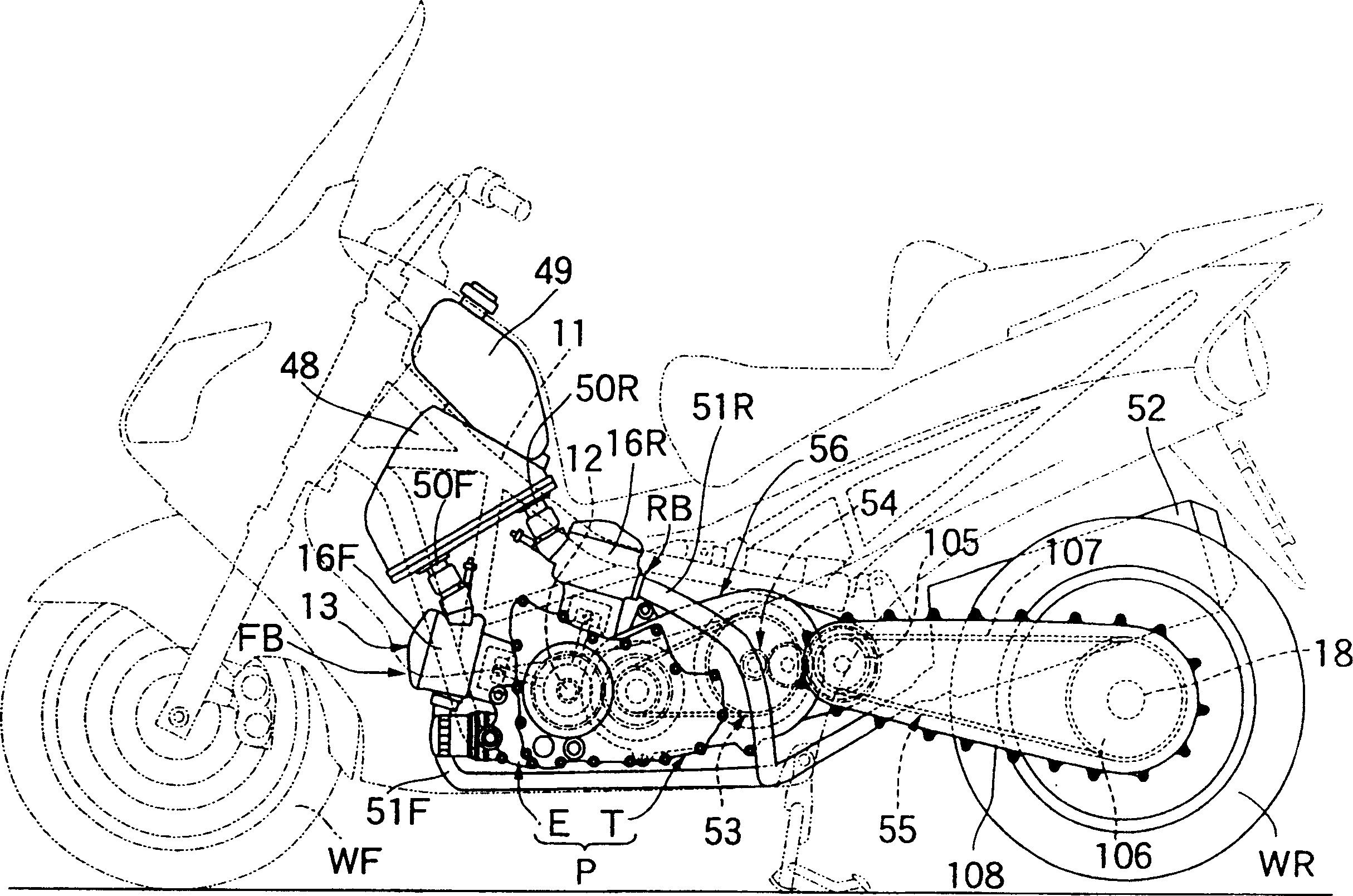
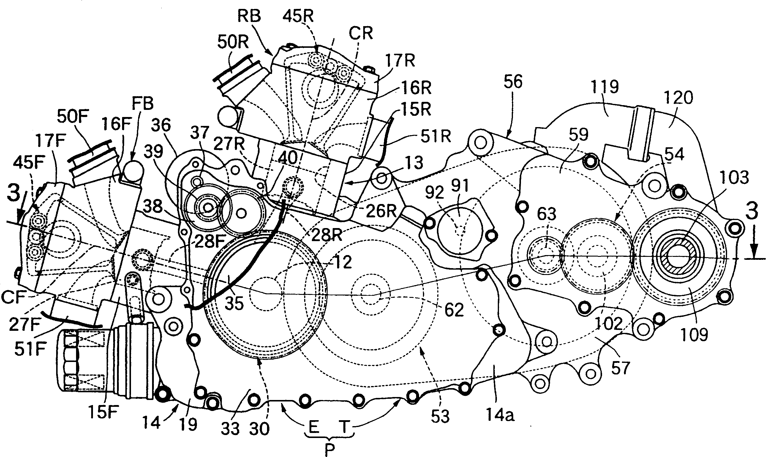
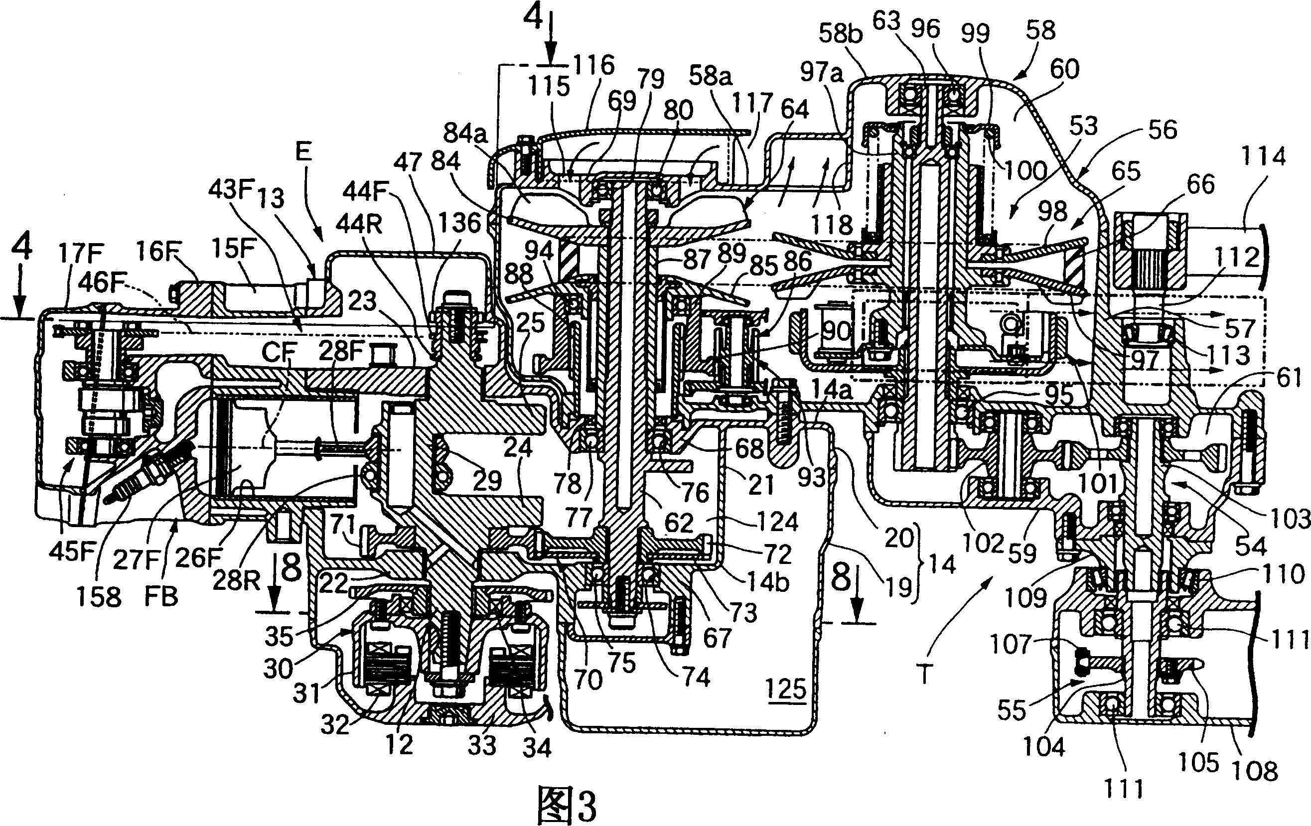
[0032] Figure 1-11 represent an embodiment of the present invention, figure 1 For a side view of a motorcycle, figure 2 for following with figure 1 The side view of the removed part of the power assembly seen in the same direction, Figure 3 is along figure 2 A cross-sectional view of line 3-3 in, Figure 4 It is a cross-sectional view along line 4-4 in Fig. 3, and Fig. 5 is along Figure 4 In view of the 5-5 line, Image 6 It is a figure corresponding to FIG. 5 in which the state of the swing arm is omitted, Figure 7 It is a sectional view along line 7-7 in Fig. 5, Figure 8 It is a sectional view along line 8-8 in Fig. 5, Figure 9 for along Figure 4 The sectional view of line 9-9 in, Figure 10 for along Figure 4 sectional view of line 10-10 in, Figure 11 for along Fi...


PUM


Abstract

To compact a combustion chamber and downsize a cylinder head in an overhead cam engine, wherein a cam shaft is provided between intake and exhaust valve springs and is rotatably supported by the cylinder head; and wherein the cam shaft is provided with a first cam to drive one of an intake valve and an exhaust valve and is provided with a second cam to drive the other of the intake valve and the exhaust valve. A cylinder head 16F supports a cam shaft 131 with its axis line approximately disposed above a cylinder axis line. A second cam 143 is disposed between intake and exhaust valve springs 129 and 130 and is formed to be smaller than a first cam 142. The first cam 142 is disposed farther from the position between the intake and exhaust valve springs 129 and 130 along the direction of the axis line of the cam shaft 131.

Description

technical field [0001] The present invention relates to an overhead cam type engine in which an intake valve and an exhaust valve are openably and closably provided on a cylinder head constituting a part of the engine body, which are directed toward The valve closing direction is energized. On the camshaft rotatably supported on the cylinder head between the valve spring on the intake valve side and the valve spring on the exhaust valve side, there are devices for driving the intake valve and the exhaust valve. A first cam for one of the gas valves and a second cam for driving the other of the intake and exhaust valves. Background technique [0002] For example, in Patent Document 1, etc., there is known an overhead cam type engine in which, in order to ensure a space for arranging a spark plug, a camshaft provided between an intake valve and an exhaust valve is directed from the cylinder axis toward the intake air. One side of the valve and exhaust valve is biased. [000...

Claims


Application Information

Patent Timeline
IPC IPC(8): F01L1/04F01L1/02F01L1/053F01L1/12F01L1/18F01L1/26F02B61/02F02B75/22F02F1/24F02F1/38F02F1/42
CPCF01L1/022F01L1/053F02B2275/20F01L2105/00F01L2001/0535F01L2820/041F02F1/38F01L1/26F02F1/4214F02B61/02F01L1/024F02B75/22F01L2305/00
Inventor 田中宏幸
Owner HONDA MOTOR CO LTD
Why Eureka
Try Eureka