
Bolt and method for forming protective layer on bolt

A bolt and thread technology, applied in the field of bolts, can solve the problems of sufficient coverage of bolts, uneven thickness of the protective layer, and waste products, etc., and achieve the effect of reducing the bite

Inactive Publication Date: 2004-09-08
SIEMENS AG
View PDF1 Cites 7 Cited by
  • Summary
  • Abstract
  • Description
  • Claims
  • Application Information

AI Technical Summary

Problems solved by technology

But this traditional method for forming such a layer of aluminum-containing protective layer on the bolt has the following disadvantages: the solution with this aluminum-containing material flows along the surface of the bolt during the drying process, which leads to The protective layer formed on the bolt has an uneven thickness
So some of these bolts are not adequately covered by this aluminum containing medium and may end up as scrap

Method used


Image

  • Bolt and method for forming protective layer on bolt

Examples


Embodiment Construction

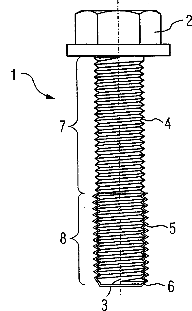
[0021] figure 1 A coated bolt 1 can be seen in . It has a screw head 2 and a threaded section 4 extending along a longitudinal axis 3 . In the illustrated embodiment, the thread section 4 extends from the head 2 to the thread start point 6 . Along its longitudinal axis 3 , the screw 1 has an upper thread section 7 and a lower thread section 8 , wherein the division between the two upper and lower thread sections 7 and 8 can be varied as desired. The screw 1 is also possible in other embodiments, for example the screw 1 has a threaded section 4 along the longitudinal axis 3 which is only partially coated with high-temperature paint. The bolt can be produced, for example, from 12% chrome steel.

[0022] The screw 1 can also be used in steam turbines and gas turbines.

[0023] The screw 1 is coated over its entire threaded section 4 with an aluminum-containing high-temperature paint 5 . The aluminum-containing high-temperature varnish does not have to be applied over the ent...


PUM


Abstract

The invention relates to a process for producing a protective layer on a bolt, in which an aluminum-containing high-temperature lacquer is first of all applied to the bolt and then cured and stoved at a defined stoving temperature. The screw thread is additionally lubricated prior to installation of the bolt. This process reduces oxidation and ultimately reduces seizing of the screw connection.

Description

technical field [0001] The present invention relates to a bolt capable of effectively preventing the tendency of seizure from increasing and a method for forming a protective layer on the bolt. Background technique [0002] Due to the high temperature in the structure of the steam turbine, some of which exceed 500°C, high-alloy bolts and nuts are often used for the mechanical connection between the components of the steam turbine. Such bolted connections are usually in a condition known as a bite. Seizure is a wear phenomenon based on adhesion which can lead to damage under high loads. Seizing of parts that fit into each other is usually the result of strong seizure. Sticking is known to occur between overtightened components. When two faces are pressed against each other under load, the interacting surfaces form a strong bond due to the locally developed high pressure and the heat generated by the motion. When this bond is released at the contact interface, only a small...

Claims


Application Information

Patent Timeline
Patent Type & Authority Applications(China)
IPC IPC(8): F01D25/24F01D25/28F16B33/00F16B33/06
CPCF16B33/008F16B33/06
Inventor 克里斯琴·布姆托马斯·林克艾伯特·施赖
Owner SIEMENS AG
Learn More