


Quick Research
Generate reliable direction feasibility study reports for your R&D in just a few steps.

Technical Q&A
Discover and master advanced knowledge NOW. Basics, ideas, possibilities, all at once.

Find Solutions
As an expert in R&D theories, this can generate solutions to your technical problems instantly.

Evaluate Feasibility
Analyze your overall solution with one click, know your potential R&D risks in advance.

Monitor Landscape
Get weekly tech updates, stay abreast of the latest tech innovations and key insights.
Inductive position detector
A detector, inductive technology, applied in the field of inductive position detectors, which can solve the problems of waste, wrong time, etc.
- Summary
- Abstract
- Description
- Claims
- Application Information
AI Technical Summary
Problems solved by technology
Method used
Image

Examples
Embodiment Construction
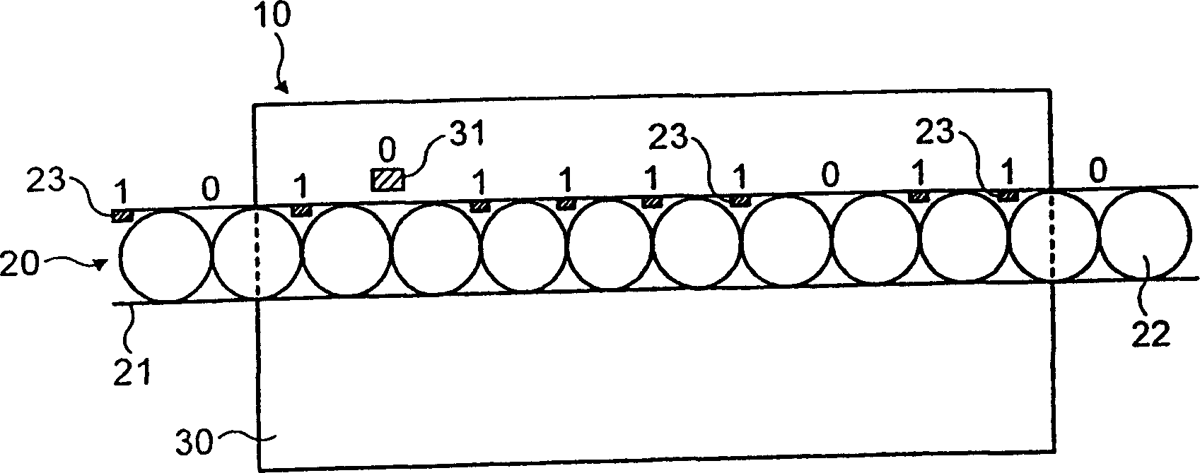
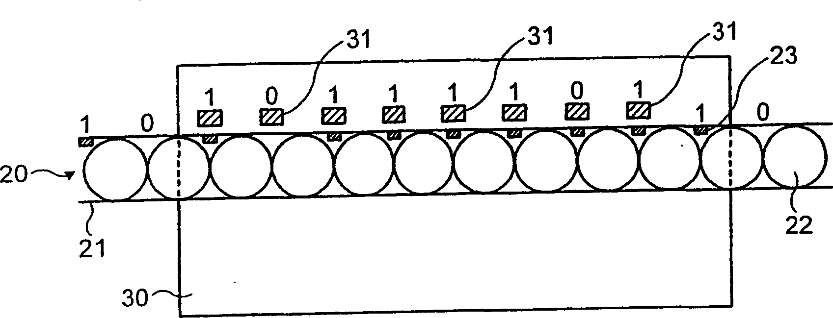
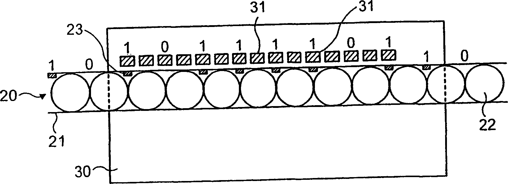
[0032] Such as figure 1 The illustrated position detector 10 includes a longitudinally extending scale 20 and a sensor 30 . The sensor 30 surrounds the scale 20 and is movable along the length of the scale 20 .
[0033] The scale 20 comprises a tube 21 of non-magnetic material housing a series of magnetic beads 22 housed in point contact in the tube 21 and constrained to prevent the beads 22 from relative motion between them. Sensor 30 includes a plurality of transmit coils (not shown) and a plurality of pickup coils (not shown). The transmit coils are used to induce a magnetic field along the line of contacts of the beads 22, and the pick-up coils are arranged to detect changes in the magnetic field as the beads 22 move relative to the pick-up coils. A detector circuit (not shown) is used to analyze the signaling to give position information. Such devices are well known in the art and one such device has been described in GB1513567. Specifically, the total position value...
PUM
 Abstract
Description
Claims
Application Information
 - R&D Engineer
- R&D Manager
- IP Professional
- Industry Leading Data Capabilities
- Powerful AI technology
- Patent DNA Extraction
Browse by: Latest US Patents, China's latest patents, Technical Efficacy Thesaurus, Application Domain, Technology Topic, Popular Technical Reports.
© 2024 PatSnap. All rights reserved.Legal|Privacy policy|Modern Slavery Act Transparency Statement|Sitemap|About US| Contact US: help@patsnap.com