Water-blending process device

A technology of water flow and flow, which is applied in the direction of wellbore/well valve device, production fluid, wellbore/well parts, etc. It can solve the problems of shortening the service life of the valve, failing to achieve the expected effect, and easy to shatter the valve. , to achieve the effect of rapid adjustment, good sealing performance, quick installation and maintenance

Inactive Publication Date: 2004-07-28
李玲
View PDF0 Cites 3 Cited by
  • Summary
  • Abstract
  • Description
  • Claims
  • Application Information

AI Technical Summary

Problems solved by technology

[0002] The existing water mixing process uses valves to control the flow rate of the mixed water. The problem with this method is that it is difficult to control and adjust the flow rate with a valve, and the flow rate is also unstable, often failing to achieve the desired effect; ②It is easy to shave and damage the valve, causing running, popping, leaking and dripping, and shortening the service life of the valve

Method used


Image

  • Water-blending process device
  • Water-blending process device

Examples


Embodiment Construction

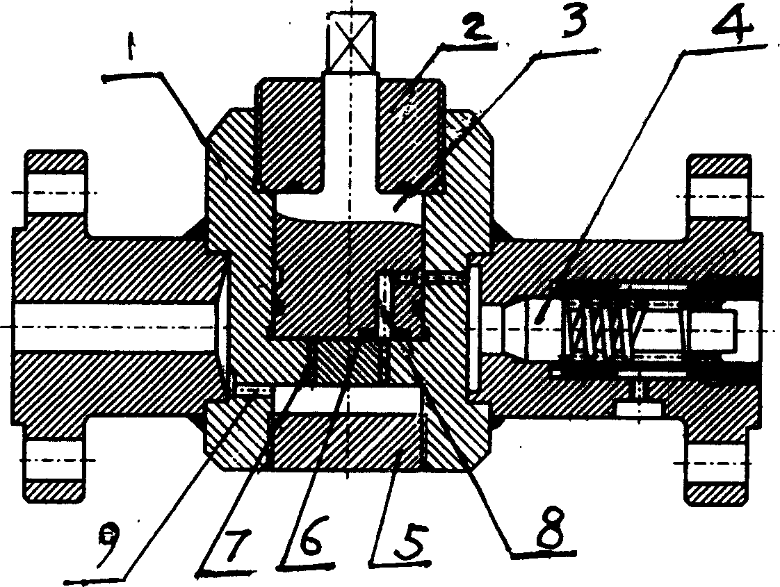
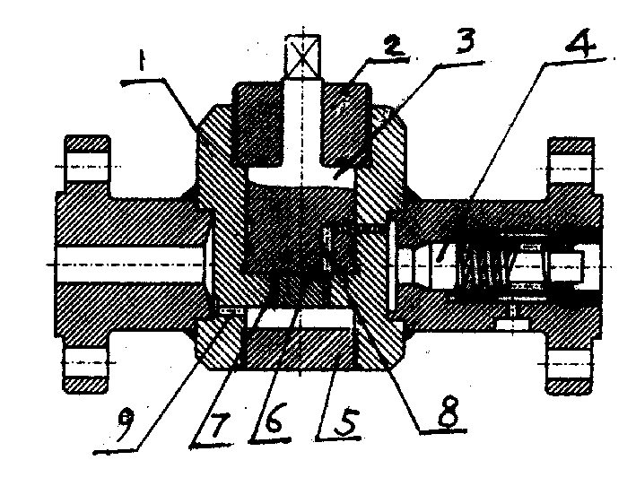
[0013] Referring to the accompanying drawings, a water-mixed flow device includes a housing 1 and a check valve 4 connected to the housing 1. The housing 1 is cylindrical, and the partitions of the upper and lower chambers are arranged with 1-12 (shown as 6 in the figure) flow channels 7 with different apertures, the lower cavity is provided with a water flow channel 9 connected with the water inlet channel of the shell 1, a bottom cover 5 is installed at the end, and a rotating channel is installed in the upper cavity. The body 3 is provided with a vertically folded channel 8 communicating with each flow channel on the partition plate and the check valve 4 installed on the outlet of the housing, and a sealing cover 2 is installed on the upper end of the housing 1 .

[0014] The rotating body 3 of the present invention is a cylindrical structure, installed in the upper cavity of the housing 1 , and a rotating rod is installed in the center of its upper end, and the rotating rod...


PUM


Abstract

The present invention relates to a water-blending process equipment. It includes a shell body and a check valve connected on the shell body. The described shell body is made into the form of cylinder, and has an upper and lower cavity structure, on the partition board of upper and lower cavities 1-12 flow-passing hole channels with different hole diameters are circumferentially distributed on the lower cavity the water-passing pore channel communicated with water-feeding channel of the shell body is set, its end portion is equipped with bottom cover, a rotating body is mounted in the upper cavity, and the rotating body also is equipped with pore channels which are communicated with all the flow-passing pore channels on the described partition board and check valve set o the outlet of the shell body, and the upper end of the shell body is equipped with seal cover.

Description

1. Technical field [0001] The invention relates to a special working technology for oil exploitation, in particular to a water mixing process device. 2. Background technology [0002] The existing water mixing process uses valves to control the flow rate of the mixed water. The problem with this method is that it is difficult to control and adjust the flow rate with a valve, and the flow rate is also unstable, often failing to achieve the desired effect; ②It is easy to shave and damage the valve, causing running, popping, leaking and dripping, and shortening the service life of the valve. 3. Contents of the invention [0003] The technical problem to be solved by the present invention is to provide a water mixing process device that can accurately control the flow rate, is easy to adjust, easy to operate, and has an ideal effect. [0004] The technical scheme for solving the problem of the present invention is an improved water mixing process device, which includes a casi...

Claims


Application Information

Patent Timeline
IPC IPC(8): E21B34/02E21B43/20
Inventor 张俊赵洪兵李汝森巴军张守武王立敏李玲
Owner 李玲
Why Eureka
Try Eureka