
Turbine compressor

A technology of a turbo compressor and a compression mechanism, applied in the field of turbo compressors, can solve the problems of damage to the scroll lap 121b, damage, poor working conditions, etc., and achieve the effect of preventing poor working conditions

Inactive Publication Date: 2004-07-14
DAIKIN IND LTD
View PDF1 Cites 5 Cited by
  • Summary
  • Abstract
  • Description
  • Claims
  • Application Information

AI Technical Summary

Problems solved by technology

However, if such a structure is made, the refrigerant in the refrigerant circuit is directly sucked into the compression chamber from the suction pipe 114, so for example, when the refrigerant contains impurities, the fixed turbine 121 and the movable turbine 122 are mixed in. Engaged in the state of the impurity, as a result, it may lead to poor working conditions and damage to the scroll lap joints 121b, 122b
Furthermore, when the liquid refrigerant is also sucked in during startup, the liquid refrigerant is directly sucked into the compression chamber, and there is still a risk of poor working conditions and damage to the scroll-shaped lap joints 121b, 122b.

Method used


Image

  • Turbine compressor
  • Turbine compressor
  • Turbine compressor

Examples


Embodiment Construction

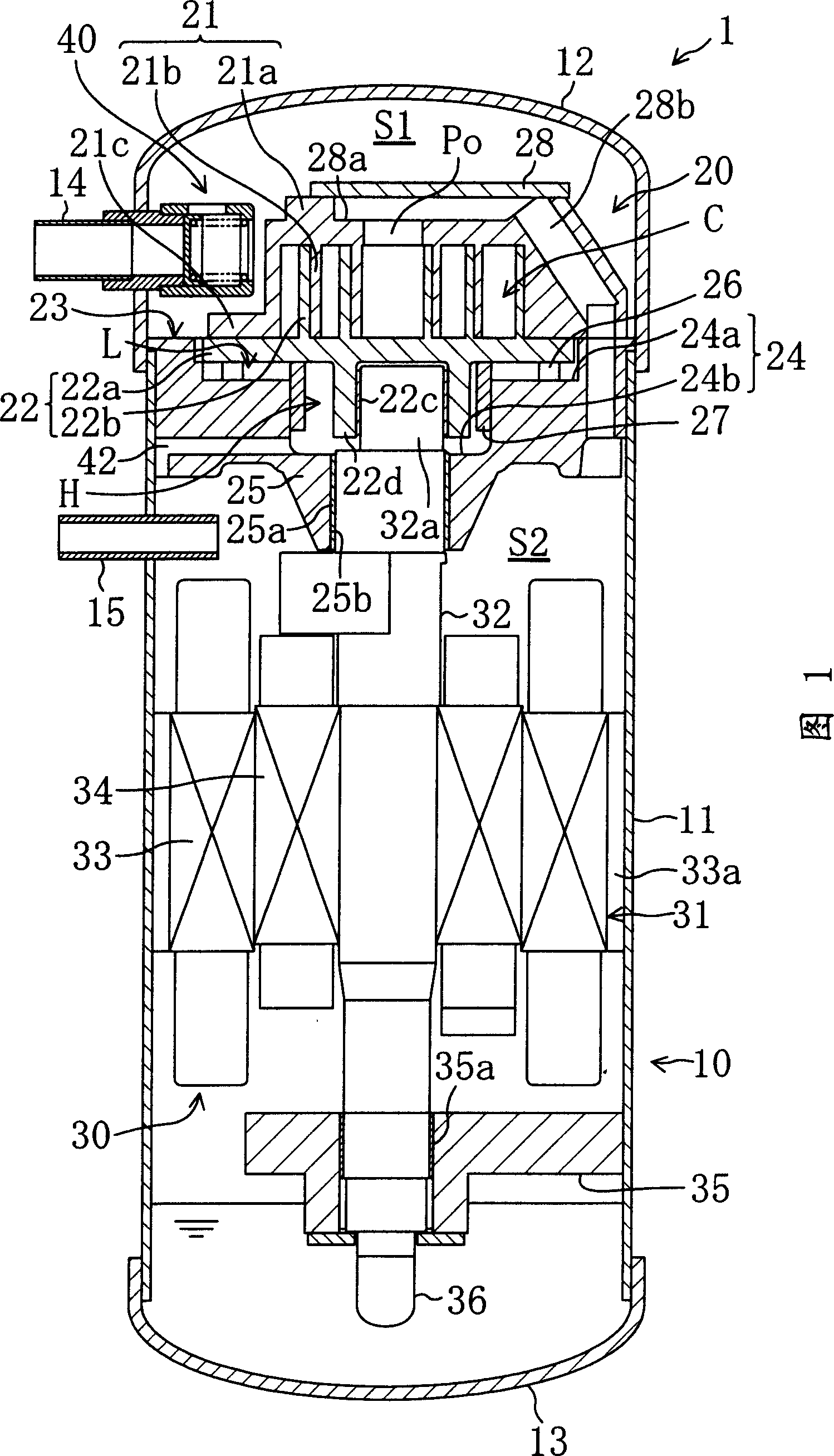
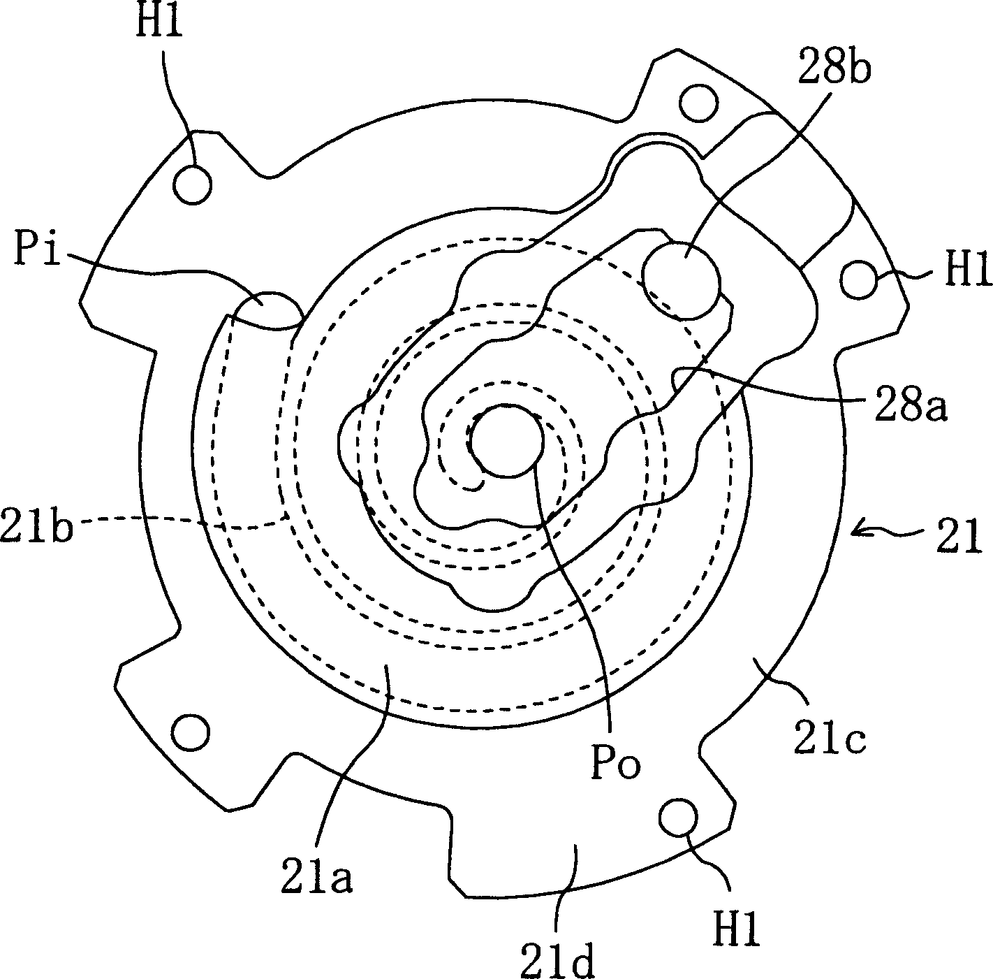
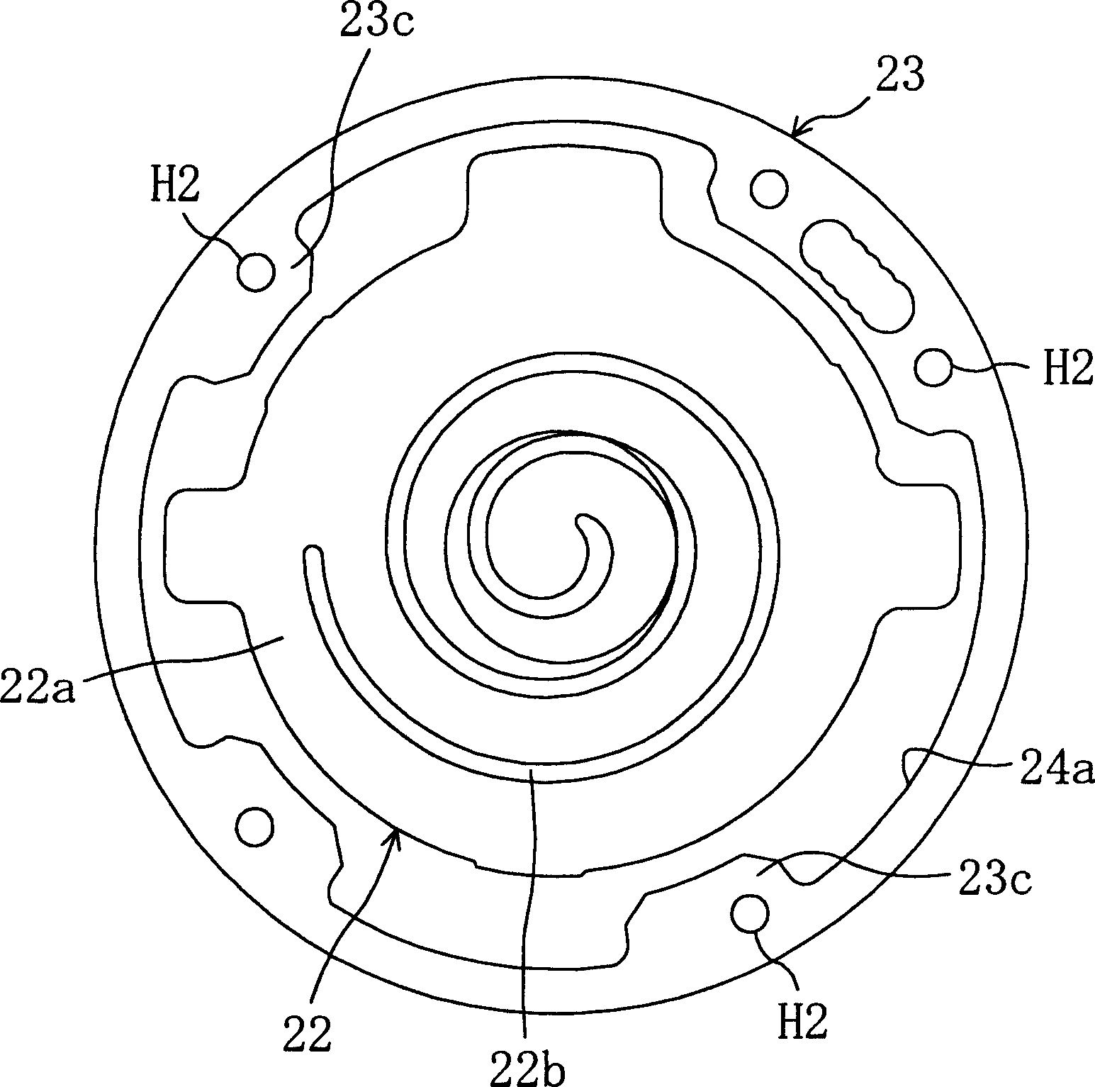
[0039] Hereinafter, a turbo compressor according to an embodiment of the present invention will be described in detail with reference to the drawings. FIG. 1 is a structural sectional view of the turbo compressor 1 .

[0040] The turbo compressor 1 performs, for example, a compression process of a vapor compression refrigeration cycle in a refrigerant circuit of an air conditioner. As shown in FIG. 1 , a compression mechanism 20 and a driving mechanism 30 for driving the compression mechanism 20 are installed in the casing 10 of the turbo compressor 1 . The case 10 is composed of a vertically long cylindrical shell 11 , an upper end plate 12 joined to the upper end of the shell 11 , and a lower end plate 13 joined to the lower end of the shell 11 . The upper end plate 12 and the lower end plate 13 are respectively welded on the shell 11, and the shell 10 is in a sealed state.

[0041] The compression mechanism 20 includes: a fixed turbine 21 , a movable turbine 22 , and a sl...


PUM


Abstract

The present invention discloses a kind of turbocompressor. Between the non-return valve set in the opened mouth part of the suction pipe inside the turbocompressor casing and the compression mechanism, one suction space is formed. The gas is first sucked to the suction space and then sucked into the compression mechanism, and this can prevent impurity and liquid refrigerant from being sucked directly into the compression mechanism to avoid malfunction of the compression mechanism, damage of the swirl overlapping, etc.

Description

technical field [0001] The present invention relates to a turbo compressor, in particular to a guide structure for guiding suction gas into a shell. technical background [0002] Hitherto, as disclosed in Japanese Laid-Open Patent Publication No. Hei 5-1679, a turbo compressor is used to compress refrigerant in a refrigerant circuit that performs a refrigerating cycle. Such as Figure 9 As mentioned above, the shell 110 of the turbo compressor 100 is equipped with a compression mechanism 120 and a motor 131 for driving the compression mechanism 120 . In the illustrated example, the motor 131 is arranged below the compression mechanism 120 . [0003] The compression mechanism 120 includes: a fixed turbine 121 and a movable turbine 122 having spiral laps 121b, 122b engaged with each other, a housing 123 supporting the two turbines 121, 122, and the housing 123 is fixed inside the shell 110 . In this figure, the fixed turbine 121 is fixed on the top of the sleeve 123 with th...

Claims


Application Information

Patent Timeline
Patent Type & Authority Applications(China)
IPC IPC(8): F04C18/02F04C29/00
Inventor 梶尾干央加藤胜三古庄和宏
Owner DAIKIN IND LTD
Learn More