Multi channel digital signal generator
A digital signal and generator technology, applied in the field of digital communication, can solve the problems of difficult system integration, low timing accuracy, and inability to generate many channel waveforms.
- Summary
- Abstract
- Description
- Claims
- Application Information
AI Technical Summary
Problems solved by technology
Method used
Image

Examples
Embodiment 1
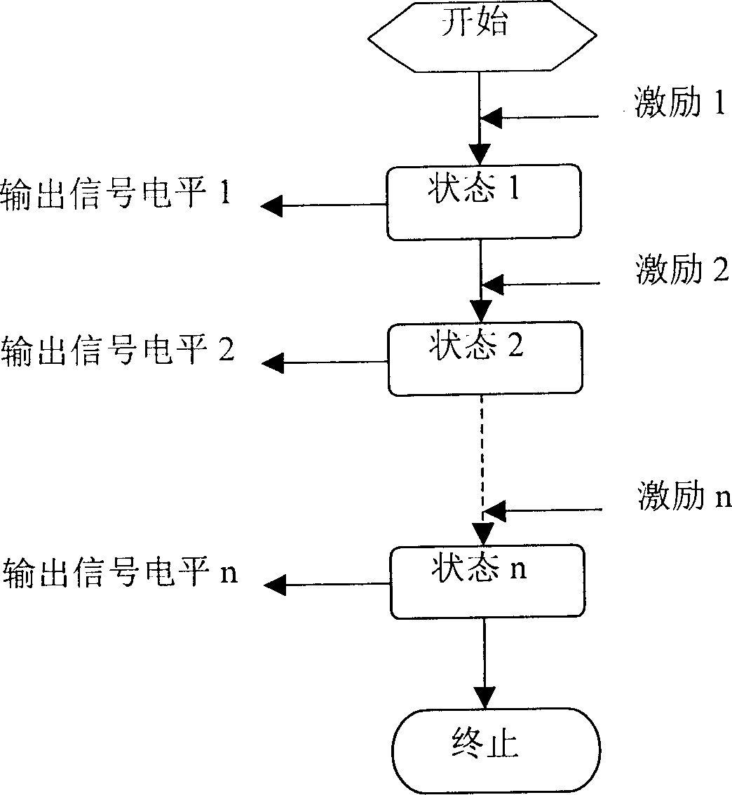
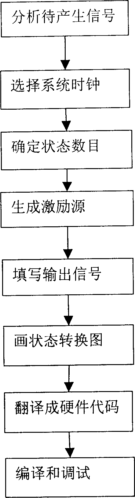
[0029] as attached figure 1 and 2 . The present invention includes analyzing the signal module to be generated, selecting the system clock module, determining the state number module, generating the excitation source module, filling in the output signal module, drawing the state transition diagram module, translating into a hardware code module, compiling and debugging module, characterized in that: : The finite state machine completes each state transition sequentially under the drive of parameters determined by analyzing the signal module to be generated, selecting the system clock module and determining the number of states, and then outputs the specified number and Specify the length and relative position of the digital signal, and assign values to each state output signal by filling in the output signal module according to the high and low levels of the corresponding time period of the output signal, and then draw the state transition diagram module to facilitate readi...
Embodiment 2
[0036] Such as Figure 4 . The selection system clock module of the present invention is the core of the finite state machine, which drives the automatic operation of the finite state machine, and its clock frequency determines the frequency and precision of the output waveform.
[0037] The longest clock period in the present invention cannot exceed the frequency of the output signal.
[0038] When the selection system clock module of the present invention generates corresponding two output signals, the clock period is minutes.
[0039] in the attached Figure 4 Among them, two output signals are generated, and their clock periods are 10ns and 20ns.
Embodiment 3
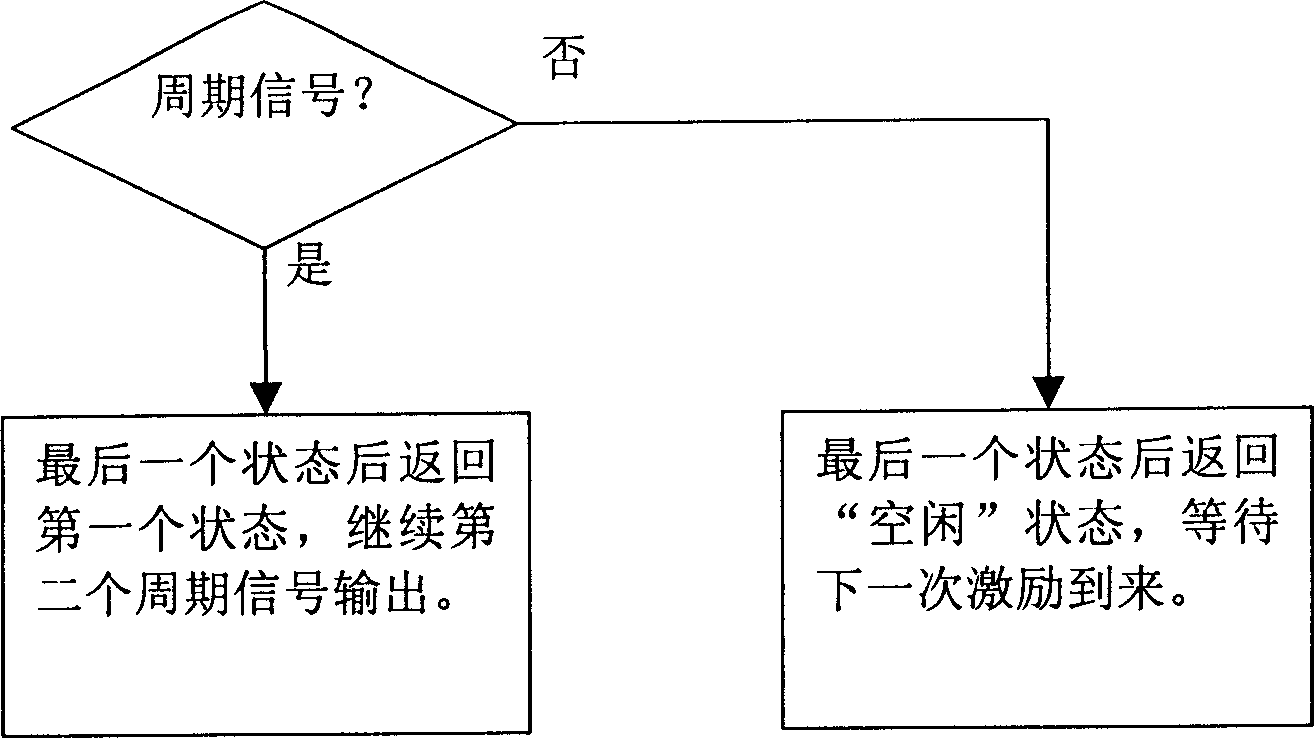
[0041] produced as Figure 6 The output of periodic signals W1 and W2 shown has a signal resolution of 10ns, that is, 100MHz, so a 100MHz clock should be selected, and the minimum co-multiple cycle of W1 and W2 is 30ns, so the number of selected states is 3. Since it is a self-excited periodic signal, no excitation signal is used. combined with Figure 5 , the upper part shows an input signal CLK, two input signals W1 and W2, S1, S2, and S3 are the three states of the finite state machine, and the arrow indicates the direction of conversion. Figure 5 The box on the right of , indicates the output signal status in various states.
[0042] It is implemented in VHDL or Verilog language, with strong readability and portability.
PUM
 Abstract
Description
Claims
Application Information
 - R&D
- Intellectual Property
- Life Sciences
- Materials
- Tech Scout
- Unparalleled Data Quality
- Higher Quality Content
- 60% Fewer Hallucinations
Browse by: Latest US Patents, China's latest patents, Technical Efficacy Thesaurus, Application Domain, Technology Topic, Popular Technical Reports.
© 2025 PatSnap. All rights reserved.Legal|Privacy policy|Modern Slavery Act Transparency Statement|Sitemap|About US| Contact US: help@patsnap.com