Permanent magnet device for low-voltage electrical apparatus

A technology for permanent magnets and low-voltage electrical appliances, which can be used in permanent magnets, snap-action devices, stepless relays, etc., and can solve problems such as failures

Inactive Publication Date: 2004-06-02
孟令春
View PDF18 Cites 0 Cited by
  • Summary
  • Abstract
  • Description
  • Claims
  • Application Information

AI Technical Summary

Problems solved by technology

[0002] There are many patent documents on the application of permanent magnets to low-voltage electrical appliances, but almost all of these patented technologies have failed in actual production

Method used


Image

  • Permanent magnet device for low-voltage electrical apparatus
  • Permanent magnet device for low-voltage electrical apparatus
  • Permanent magnet device for low-voltage electrical apparatus

Examples


Embodiment 1

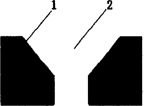
[0044] figure 1 It is a basic embodiment of the invention. In the figure, the permanent magnet 1 has a through inner hole 2; the upper part of the inner hole 2 is in the shape of a frustum, and the lower part of the inner hole 2 is in the shape of a column.

Embodiment 2

[0046]FIG. 2 is one of the embodiments created by the present invention, which is further limited on the basis of the above-mentioned basic device and some technical features are added. The upper shape of the inner hole 2 is a frustoconical shape, and the lower shape of the inner hole 2 is a cylindrical shape. The permanent magnet 1 is mounted on the plate body of the yoke plate 3 , and the nail 4 is mounted in the inner hole 2 of the permanent magnet 1 . The nail 4 is isolated from the wall of the inner hole 2 by a pad 5 .

Embodiment 3

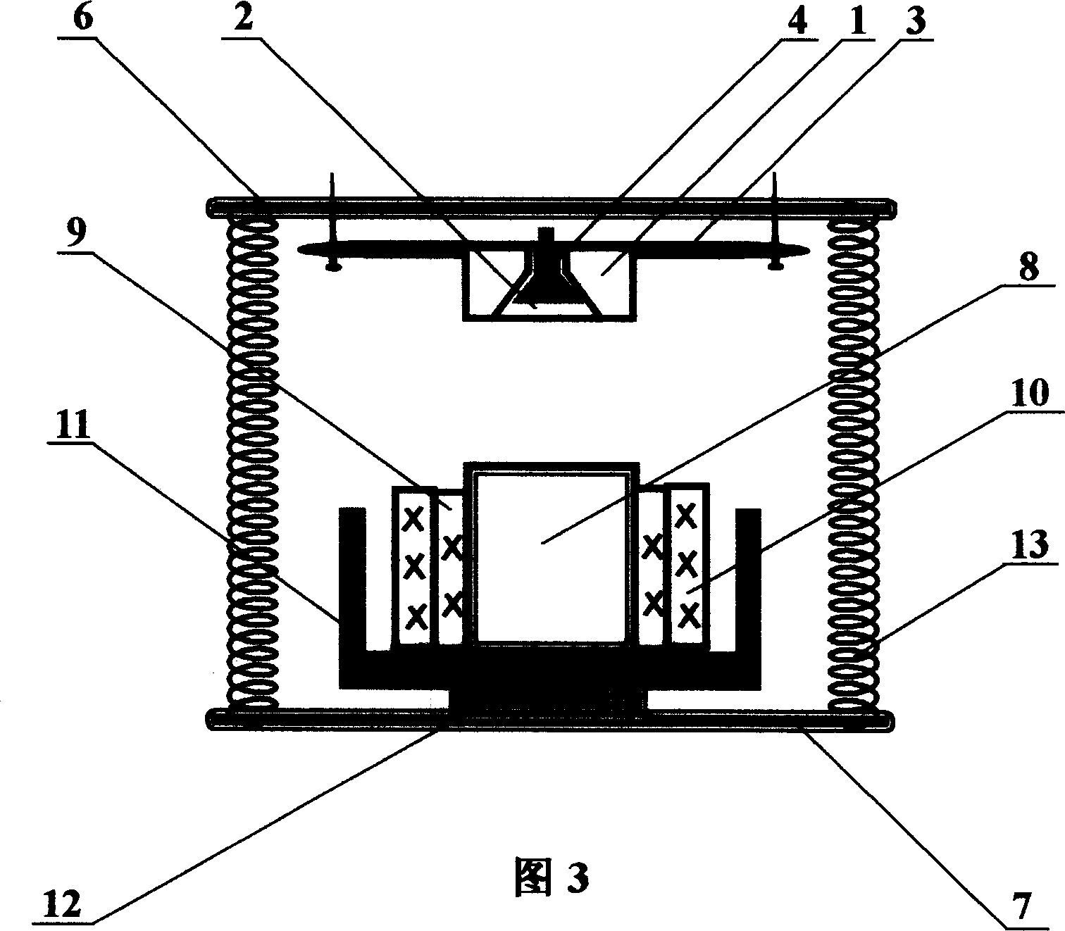
[0048] Figure 3 is another embodiment of the present invention, which is in the figure 1 Alternatively, further restrictions are made on the basis of FIG. 2 and some technical features are added. In addition, some technical features parallel to FIG. 2 are implemented. The frustoconical portion of the inner hole 2 occupies 2 / 3 of the depth of the inner hole 2 , and the cylindrical portion of the inner hole 2 occupies 1 / 3 of the depth of the inner hole 2 . The permanent magnet 1 is mounted on the plate body of the yoke plate 3 , and the nail 4 is mounted in the inner hole 2 of the permanent magnet 1 . The top surface of the nail 4 is lower than the upper surface of the permanent magnet 1 , and the lower part of the nail 4 passes through the yoke plate 3 . There is no spacer 5 separating the nail 4 from the wall of the inner hole 2 , and the nail 4 is in direct contact with the wall of the inner hole 2 . The choke plate 3 is fixed on the base of the upper base 6 ; a wire core 8...


PUM


Abstract

The invention discloses a permanent magnetic device for low-voltage electrical apparatus characterized by that, a through bore is arranged on the permanent magnet, the upper shape of the bore is frustum, and the lower shape of the bore is column. The permanent magnetic bore according the invention is not equivalent to the mere column or frustum shape bore of the ring form permanent magnetic in that, the wall of the latter has magnetic attracting force, while the wall portion of the former has no or smaller magnetic attracting force.

Description

technical field [0001] The technical field to which the technical solution claimed in the present invention belongs is low-voltage electrical appliances, especially permanent magnet devices in low-voltage electrical appliances. Background technique [0002] There are many patent documents on the application of permanent magnets to low-voltage electrical appliances. However, almost all of these patented technologies have ended in failure in actual production. The reason is because a key special structure based on permanent magnets has not been studied. The existing technologies that are relatively close to the invention include: magnetic holding contactor (Patent No. ZL 01230931), permanent magnet suction type AC contactor without power consumption (Patent No. ZL00204601), energy-saving contactor (Patent No. ZL 99210484), micro-contactor Electric energy-saving reciprocating device (patent No. ZL 98205482), AC contactor without holding current (paten...

Claims


Application Information

Patent Timeline
IPC IPC(8): H01F7/02H01H5/02H01H51/01
Inventor 孟令春
Owner 孟令春
Why Eureka
Try Eureka