
Exhaust structure of accumulator

A battery and exhaust chamber technology, applied in the direction of structural parts, electrical components, battery pack components, etc., can solve the problems of liquid leakage, leakage of liquid exhaust nozzles, etc.

Inactive Publication Date: 2004-05-26
THE FURUKAWA BATTERY CO LTD
View PDF1 Cites 9 Cited by
  • Summary
  • Abstract
  • Description
  • Claims
  • Application Information

AI Technical Summary

Problems solved by technology

As a result, there is a concern that fluid will occasionally leak into the battery where it is not intended, such as in the filter chamber where the explosion-proof filter is located, or through the vent nozzle to the outside of the battery

Method used


Image

  • Exhaust structure of accumulator
  • Exhaust structure of accumulator
  • Exhaust structure of accumulator

Examples


Embodiment Construction

[0020] Preferred embodiments of the present invention will be described with reference to the accompanying drawings.

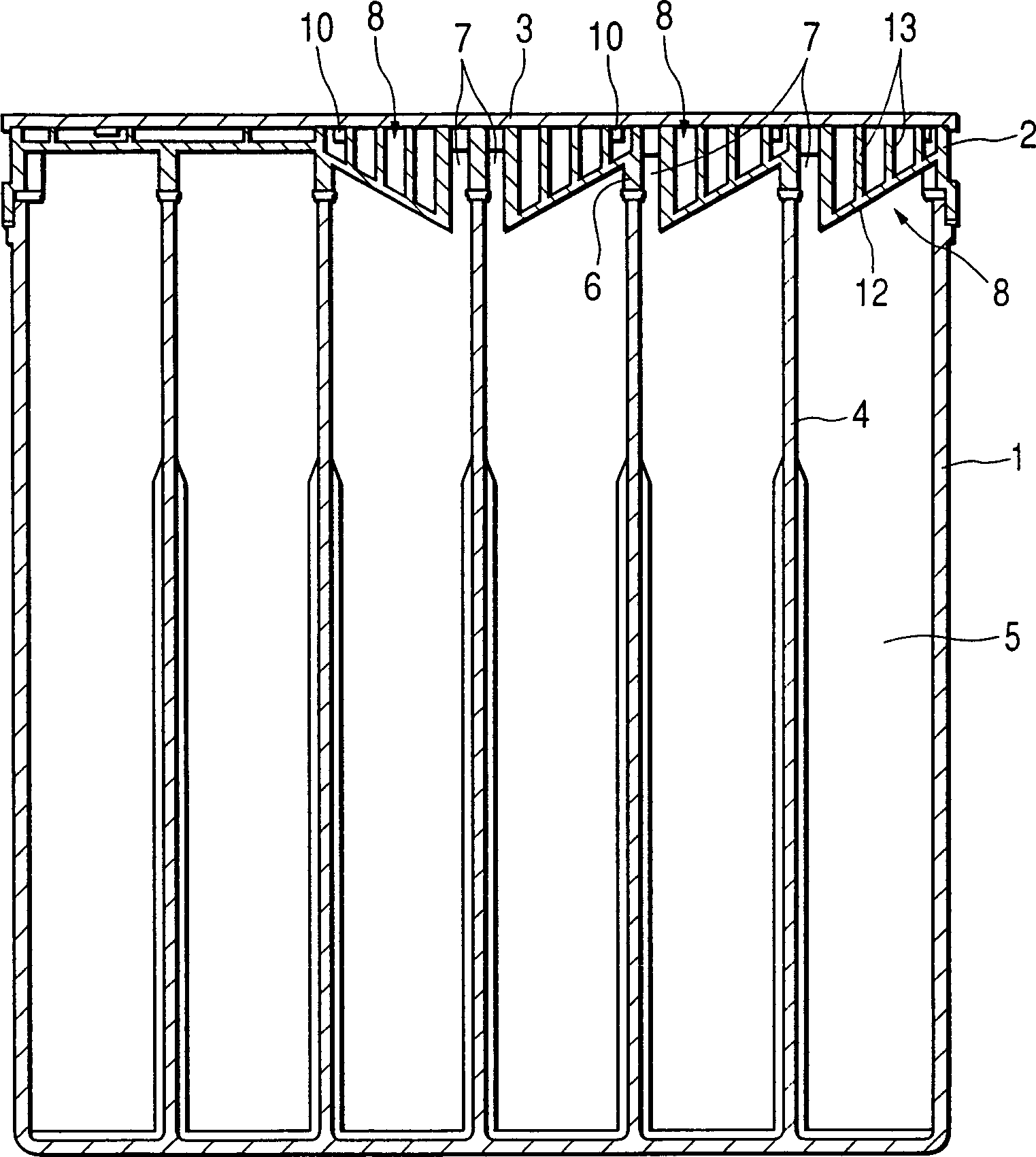
[0021] like figure 1 As shown, in the storage battery according to the first embodiment of the present invention, the interior of the battery case 1 is divided into six battery chambers 5 by the partition wall 4 . In each battery chamber 5 is accommodated an electrode plate member (not shown in the figure) in which positive and negative plates are alternately laminated and has a separator therein. The electrode plate elements in each battery chamber are connected in series through the partition wall 4 .

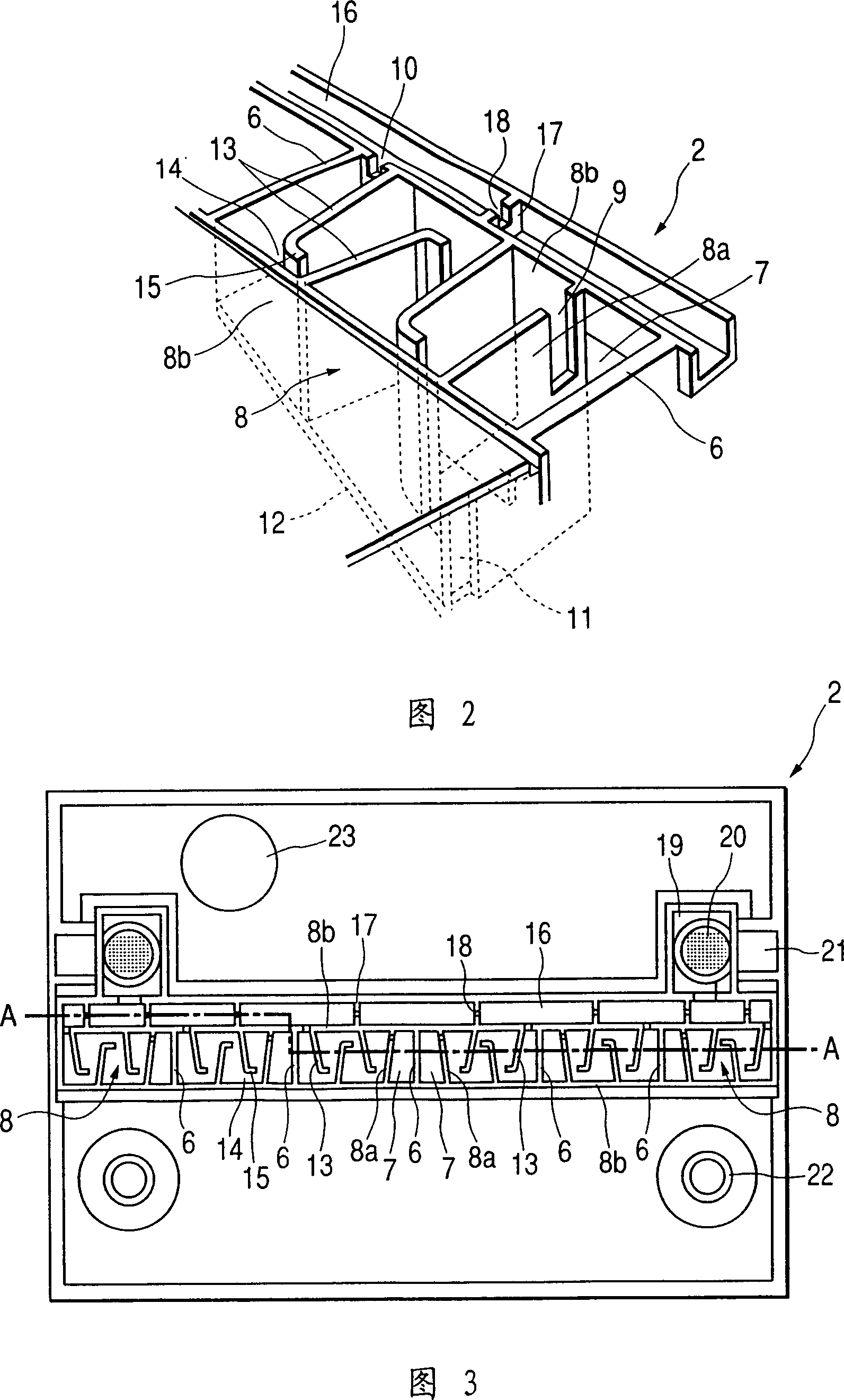
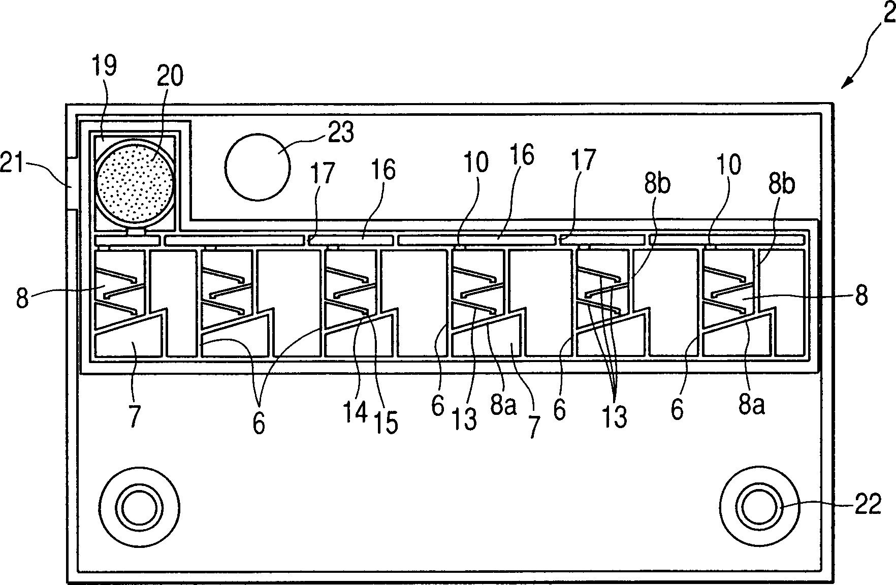
[0022] The casing 2 is welded to the battery box 1 to close the upper opening of the battery box 1 . On the opposite side of the casing 2, partition walls 6 are formed corresponding to the partition walls 4 in the battery case 1 respectively, and these partition walls 6 are welded to the partition walls 4 of the battery case 1 respectively, so that the uppe...


PUM


Abstract

An exhaust structure is provided on an upper part of a storage battery. In the structure, an exhaust chamber is formed with an inlet, through which gas generated from a cell chamber of the storage battery is introduced, a first outlet, arranged in an upper portion of the exhaust chamber and through which the gas is exhausted to an exterior of the storage battery, a second outlet, arranged in a bottom portion of the exhaust chamber and communicated with the cell chamber, side walls and a bottom wall defining the exhaust chamber. The bottom wall is slanted toward the second outlet. A plurality of plate members, which intercepts liquid contained in the gas. Each of the plate members is extended from one of the side walls such that a distal end portion faces another one of the side walls while defining a gap therebetween, and is slanted toward the second outlet so that the intercepted liquid is guided to the second outlet and returned to the cell chamber.

Description

technical field [0001] The invention relates to an exhaust structure of a storage battery. Background technique [0002] In a storage battery, especially a lead storage battery, an exhaust port is provided for exhausting internal gas generated during charging and discharging of the storage battery. In order to only exhaust gas while preventing splashing (diffusion of electrolyte due to vibration during use) and droplet leakage, it is provided in each exhaust chamber (formed in the upper part of the battery, such as in the cover of the battery) An introduction port for introducing generated gas into the exhaust chamber, and an exhaust port for discharging the introduced gas from the exhaust chamber. A plurality of splash guards are arranged in the exhaust chamber to form a labyrinth, and the bottom surface of the exhaust chamber is inclined toward the guide port. Such a structure is disclosed in Japanese utility model No. 54-131037U. [0003] In the above exhaust structure...

Claims


Application Information

Patent Timeline
IPC IPC(8): H01M50/35
CPCY02E60/12H01M2/1252Y02E60/10H01M50/35
Inventor 中野宪二矢吹修一大内久士佐野一郎
Owner THE FURUKAWA BATTERY CO LTD
Learn More