
Suface acoustic wave filter

A filter and resonator technology, applied in the direction of electrical components, impedance networks, etc., can solve the problems of low productivity, small degrees of freedom of ladder filters, etc., and achieve the effect of small insertion loss

Inactive Publication Date: 2004-05-12
NIHON DEMPA KOGYO CO LTD
View PDF1 Cites 22 Cited by
  • Summary
  • Abstract
  • Description
  • Claims
  • Application Information

AI Technical Summary

Problems solved by technology

[0005] However, since the inductor is inserted in series into the SAW resonator of the ladder filter disclosed in JP-A-5-183380, the ladder filter has a disadvantage in that, when the ladder filter is actually produced, it is necessary to The design and prototyping of the ladder filter is repeated, so the ladder filter has less freedom in design and its productivity is lower

Method used


Image

  • Suface acoustic wave filter
  • Suface acoustic wave filter
  • Suface acoustic wave filter

Examples


Embodiment Construction

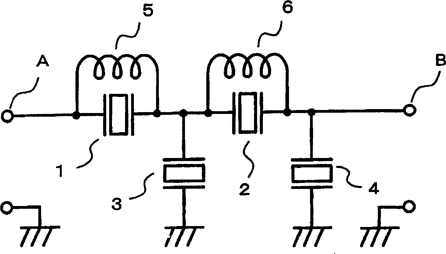
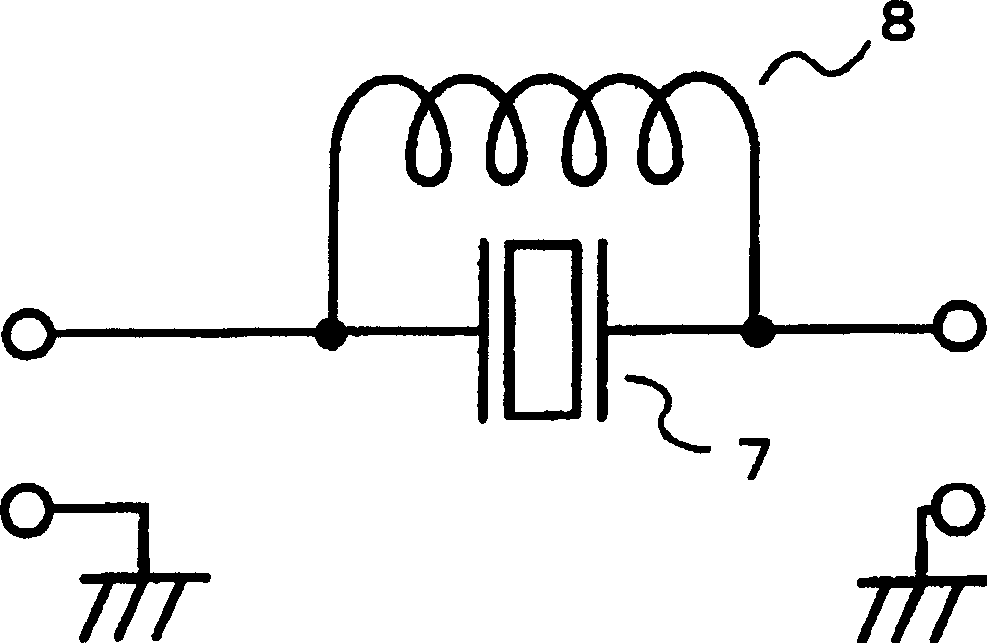
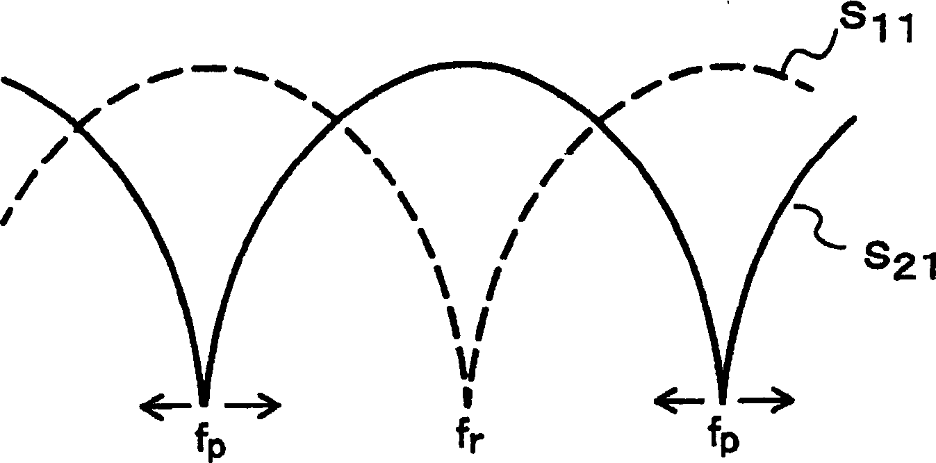
[0022] like figure 1 As shown, a SAW filter according to an embodiment of the present invention includes a two-stage ladder filter having four SAW resonators 1 to 4 . This SAW filter has an input terminal A located at the left end as shown in the figure, and an output terminal B located at the left end as shown in the figure. The SAW resonators 1, 2 on series arms are inserted in series between the input and output terminals A, B. The SAW resonator 3 on the parallel arm is inserted between the connection point between the SAW resonators 1, 2 and the ground point. The SAW resonator 4 on the parallel arm is inserted between the connection point between the SAW resonator 2 and the output terminal B and the ground point. The SAW filter also has inductors 5, 6 connected in parallel with the SAW resonators 1, 2 on the series arms, respectively.

[0023] The characteristics of an assembly including a SAW resonator on a series arm, and an inductor connected in parallel to the SAW r...


PUM


Abstract

A ladder SAW (surface acoustic wave) filter which includes a first SAW resonator disposed in a parallel arm and a second SAW resonator disposed in a series arm, has an inductor connected parallel to at least one of the first SAW resonator and the second SAW resonator. The frequency of a resonance point or an anti-resonance point of the at least one of the first SAW resonator and the second SAW resonator is adjusted by changing the inductance value of the inductor.

Description

technical field [0001] The present invention relates to a SAW (Surface Acoustic Wave) filter, and more particularly to a SAW filter having filter characteristics adjustable during assembly and providing a wide passband and a large attenuation level . Background technique [0002] In recent years, it can be seen that small communication devices such as cellular phones have been widely used by many users. Such small-sized communication equipment employs many filters as frequency selection means. Since the transverse SAW filter is relatively cheap, can miniaturize itself in size, and can be easily mass-produced, it is widely used as a filter in such a small communication device, wherein the transverse SAW The filter has an IDT (Interdigital Transducer) provided on the surface of the piezoelectric element to perform frequency component selection based on the interaction between the surface acoustic wave propagating through the surface of the piezoelectric element and the IDT. ...

Claims


Application Information

Patent Timeline
Patent Type & Authority Applications(China)
IPC IPC(8): H03H9/54H03H9/64
CPCH03H9/6483
Inventor 山本泰司恩塚辰典
Owner NIHON DEMPA KOGYO CO LTD
Learn More