Base station device, mobile station device and transmission power control method
A technology of base station equipment and transmission power, which is applied in power management, transmission control/balance, communication between multiple stations, etc., and can solve problems such as system capacity reduction
- Summary
- Abstract
- Description
- Claims
- Application Information
AI Technical Summary
Problems solved by technology
Method used
Image


Examples
Embodiment 1
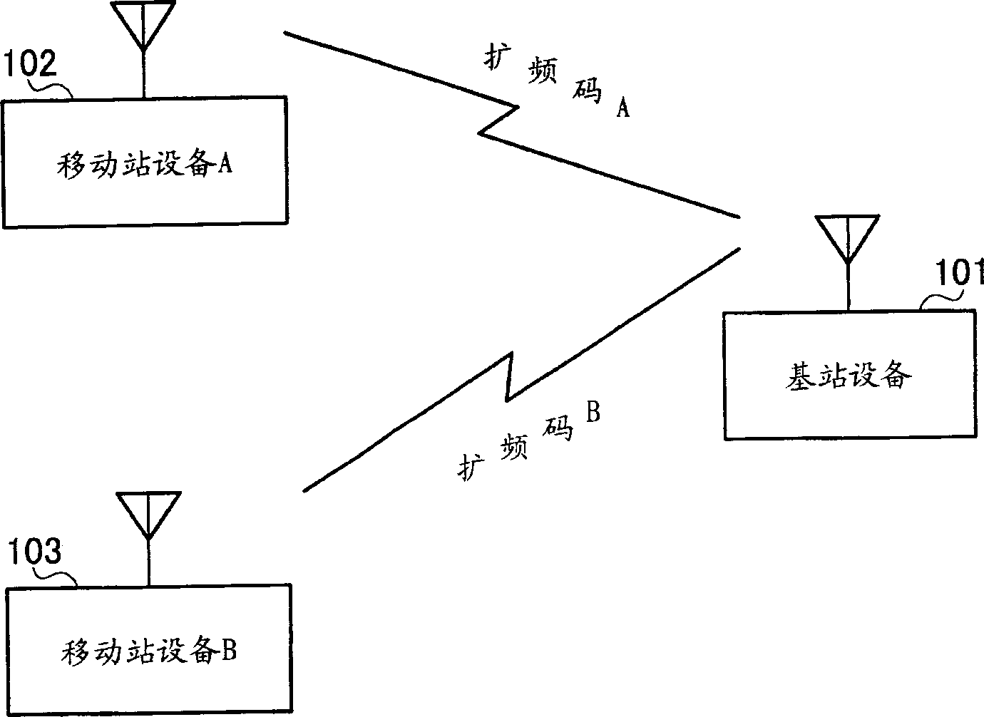
[0024] figure 1 is a conceptual diagram of a wireless communication system in which a base station device according to Embodiment 1 of the present invention and a mobile station device according to Embodiment 1 of the present invention perform communication. exist figure 1 , the base station apparatus 101 is communicating with the mobile station apparatus A 102 and the mobile station apparatus B 103.
[0025] The spreading code A is assigned to the mobile station apparatus A 102, and the spreading code B is assigned to the mobile station apparatus B 103. That is, the data transmitted and received between the base station apparatus 101 and the mobile station apparatus A 102 is spread using the spreading code A, while the data transmitted and received between the base station apparatus 101 and the mobile station apparatus B 103 is spread using the spreading code B spread spectrum.
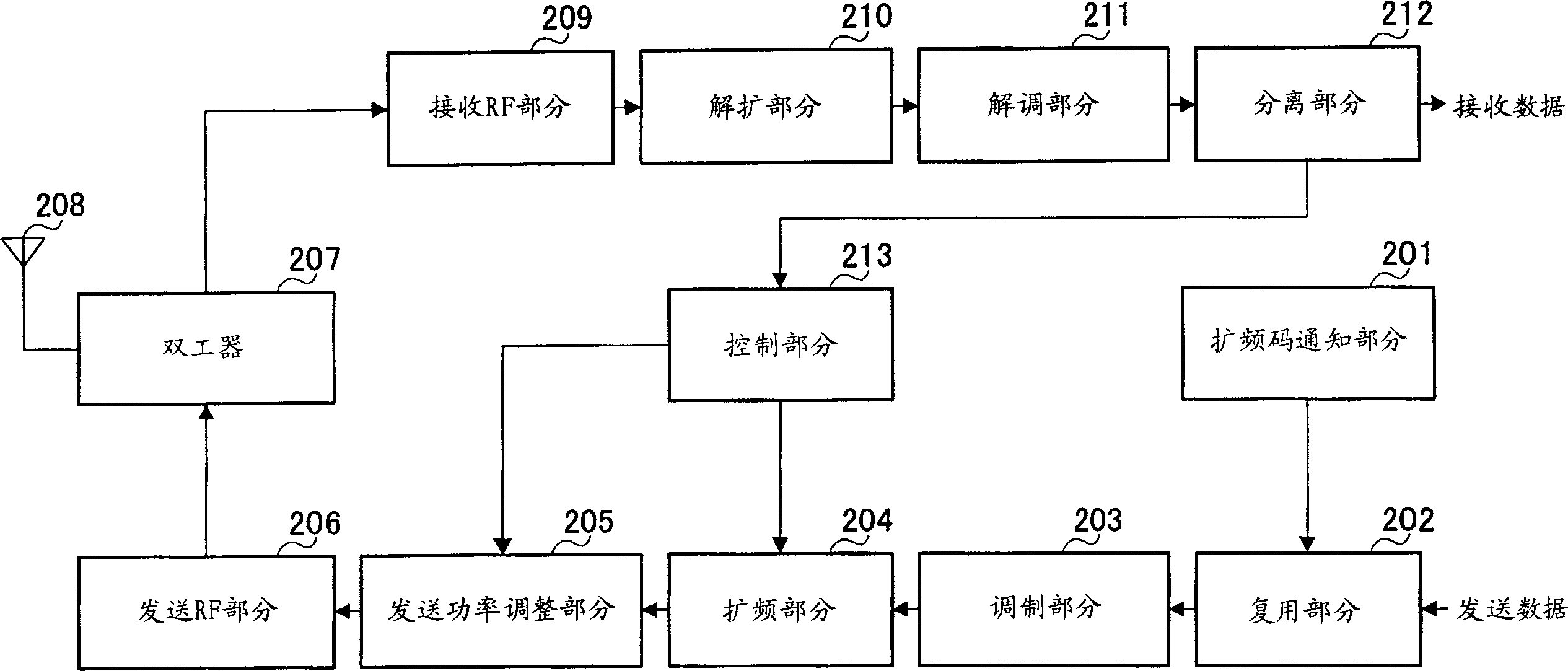
[0026] The structure of base station apparatus 101 will now be explained. figure 2 is a main...
Embodiment 2
[0068] The base station apparatus according to Embodiment 2 of the present invention has almost the same structure as the base station apparatus according to Embodiment 1, but is different in that an interfering station that exerts interference on a plurality of mobile station apparatuses is identified by comparing information on a plurality of interfering stations A mobile station device that has a significant influence on the reduction of system capacity is identified, and the transmission power to this identified mobile station device is reduced.
[0069] Figure 7 is a schematic diagram of a wireless communication system in which a base station device performs communication with a mobile station device according to Embodiment 2 of the present invention. exist Figure 7 , a base station device 401 is communicating with a mobile station device A 402 , a mobile station device B 403 , and a mobile station device C 404 .
[0070] Spreading code A is assigned to mobile station...
Embodiment 3
[0082] The base station apparatus according to Embodiment 3 of the present invention has almost the same structure as that of the base station apparatus according to Embodiment 1 or Embodiment 2, except that, when reconfirming for each mobile station apparatus whether to accept The transmitted interfering station information is used to determine the mobile station device whose transmission power should be reduced and then identify the mobile station device whose transmission power should be reduced.
[0083] Figure 10 is a main block diagram showing the structure of a base station device according to Embodiment 3 of the present invention. Figure 10 The same components as those in Embodiment 2 use the same codes as in Embodiment 2, and their detailed descriptions are omitted.
[0084] exist Figure 10 Among them, the spreading code notification section 601, in addition to performing the operations described in Embodiment 1 and Embodiment 2, also notifies each mobile station...
PUM
 Abstract
Description
Claims
Application Information
 - R&D
- Intellectual Property
- Life Sciences
- Materials
- Tech Scout
- Unparalleled Data Quality
- Higher Quality Content
- 60% Fewer Hallucinations
Browse by: Latest US Patents, China's latest patents, Technical Efficacy Thesaurus, Application Domain, Technology Topic, Popular Technical Reports.
© 2025 PatSnap. All rights reserved.Legal|Privacy policy|Modern Slavery Act Transparency Statement|Sitemap|About US| Contact US: help@patsnap.com