Method for increasing roll-type straightening machine capacity
A straightening machine and roller-type technology, which is applied in the field of forging equipment, can solve problems such as damage to transmission parts, failure to use guide rolls, and accelerated wear of work rolls, so as to save energy, improve straightening accuracy, and reduce deformation.
- Summary
- Abstract
- Description
- Claims
- Application Information
AI Technical Summary
Problems solved by technology
Method used
Image
Examples
Embodiment 1
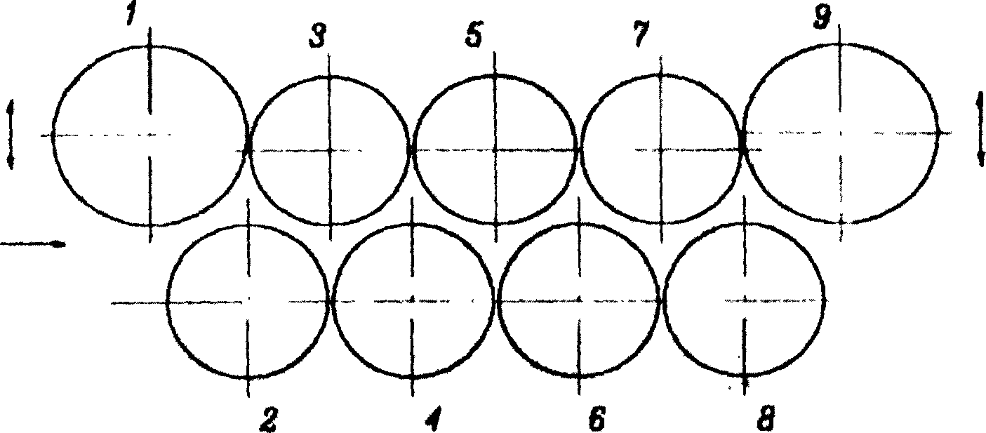
[0027] Such as figure 1 As shown, 1, 9 are guide rolls, 2, 3, 4, 5, 6, 7, 8 are work rolls. Guide rollers 1 and 9 can be raised and lowered independently. When guide rollers 1 and 9 are in the position shown in the figure, it is an ordinary nine-roll straightening machine. When guide rollers 1 and 9 rise to the upper limit, it is a seven-roll straightening machine. 1, 3, 5, The five rollers 7 and 9 can be raised and lowered together with the movable beam, which is the parallel working mode of the roller row. If the straightening capacity is increased, the load capacity of the work roll system needs to be increased, and one or several combinations of increasing the work roll distance, the work roll diameter, the number of backup rolls, and the load capacity of the backup rolls are comprehensively adopted. If the rectification capacity is not increased, the power of the main motor and the maximum design load of the machine’s force-bearing parts frame, movable beam, fixed beam,...
Embodiment 2
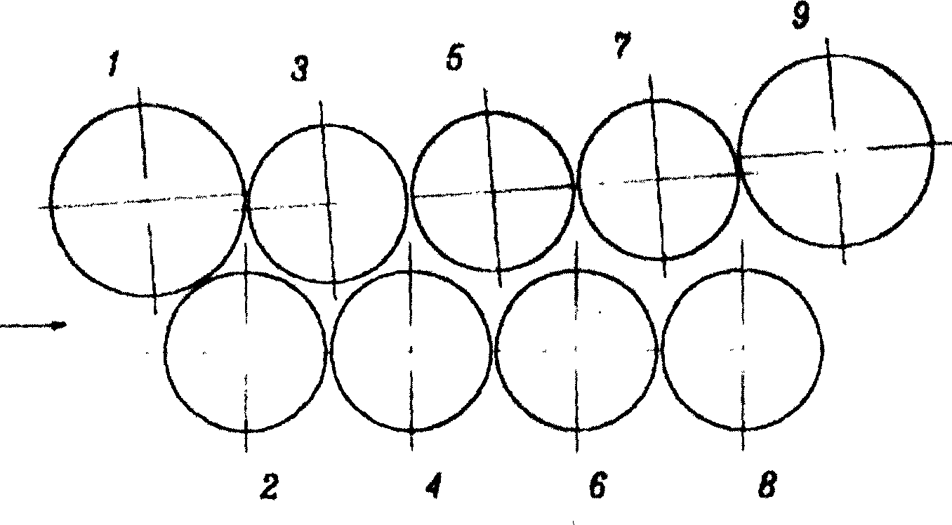
[0029] Such as figure 2 As shown, the work is in the state with the largest number of rolls. The five rollers 1, 3, 5, 7, and 9 in the upper row are tilted with the movable beam as a whole, and all nine rollers participate in the correction work. The main drive adopts the split-roller drive technology, and the main drive is not shown in the figure.
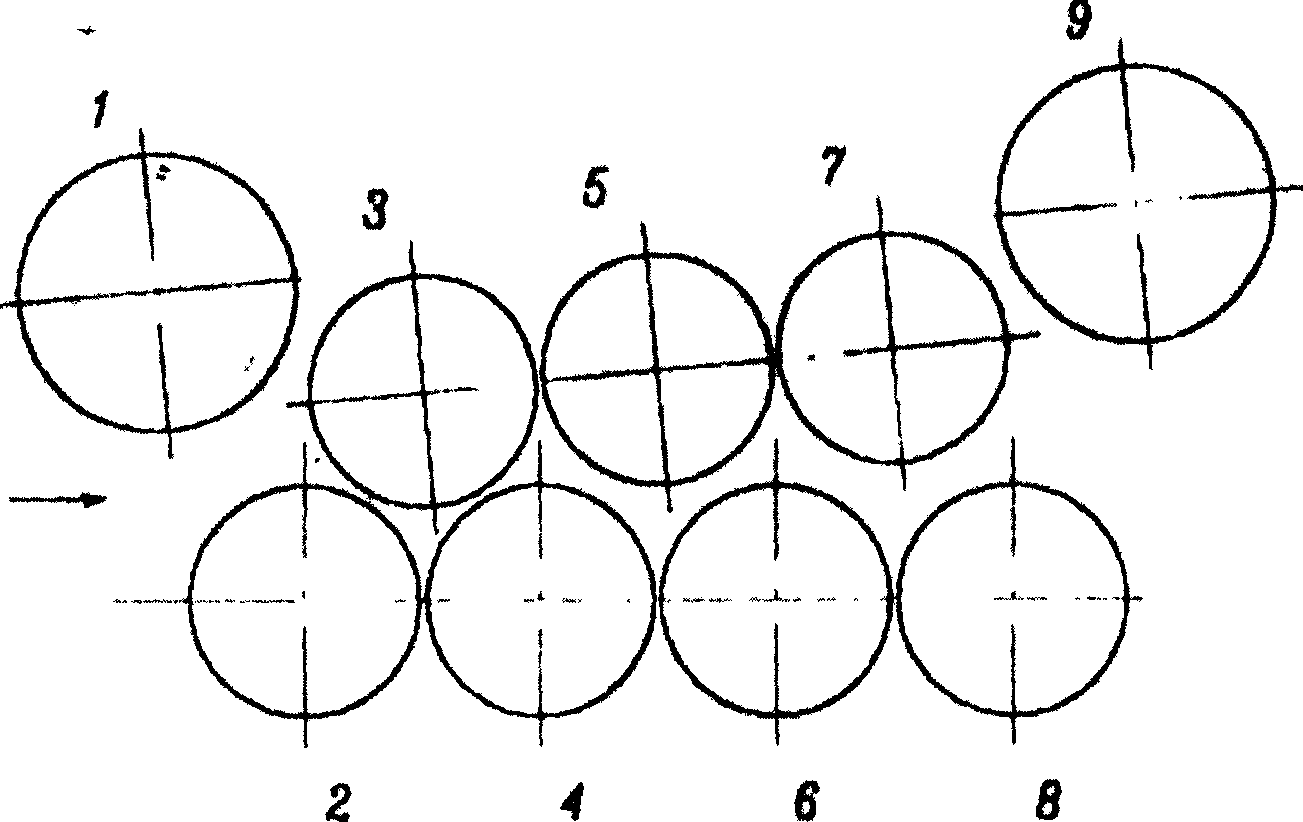
[0030] Such as image 3 As shown, the work is in a state where the number of rolls is reduced. The guide rollers 1 and 9 rise to the limit position and do not participate in the straightening work. The three working rollers in the upper row are tilted with the movable beam as a whole to adjust the opening of the material in and out. At this time, a total of seven rollers participate in the straightening work. The main drive adopts the split-roller drive technology. When the correction load increases, the loads of rollers 2 and 8 become side rollers with small loads, the loads of rollers 3 and 7 increase little or not, and the lo...
Embodiment 3
[0034] If there is no need to increase the straightening capacity of the machine, the load capacity of the work roll system may not be increased, but the power of the main motor and the maximum design load of the machine's stress-bearing component frame, movable beam, fixed beam, etc. may be reduced to save energy, reduce costs or only The power of the main motor is reduced, and the frame, movable beam, and fixed beam are still designed according to the maximum number of rollers, reducing the deformation of the machine's stressed parts and reducing the impact of the machine's elastic deformation on the accuracy of thick plate straightening.
PUM
 Abstract
Description
Claims
Application Information
 - R&D Engineer
- R&D Manager
- IP Professional
- Industry Leading Data Capabilities
- Powerful AI technology
- Patent DNA Extraction
Browse by: Latest US Patents, China's latest patents, Technical Efficacy Thesaurus, Application Domain, Technology Topic, Popular Technical Reports.
© 2024 PatSnap. All rights reserved.Legal|Privacy policy|Modern Slavery Act Transparency Statement|Sitemap|About US| Contact US: help@patsnap.com


