
Magnetic recording method and apparatus, device for determining coercive force of magnetic recording medium

A magnetic recording medium, diamagnetic technology, applied in the recording/reproducing/deleting method, magnetic recording, recording of information on tapes, etc., can solve the problem of spending a lot of time, unable to obtain diamagnetic force, etc.

Inactive Publication Date: 2004-03-17
HITACHI OMRON TERMINAL SOLUTIONS CORP
View PDF5 Cites 3 Cited by
  • Summary
  • Abstract
  • Description
  • Claims
  • Application Information

AI Technical Summary

Problems solved by technology

[0019] However, Patent Document 1 has a problem that since the magnetic card must be transferred several times in order to determine an appropriate write current, the determination process takes a lot of time
[0023] However, in this case, even when an abnormality occurs in the magnetic information used to determine the coercive force and written on the magnetic card, the determination of the magnetic force is performed as it is, so that the normal coercive force cannot be obtained

Method used

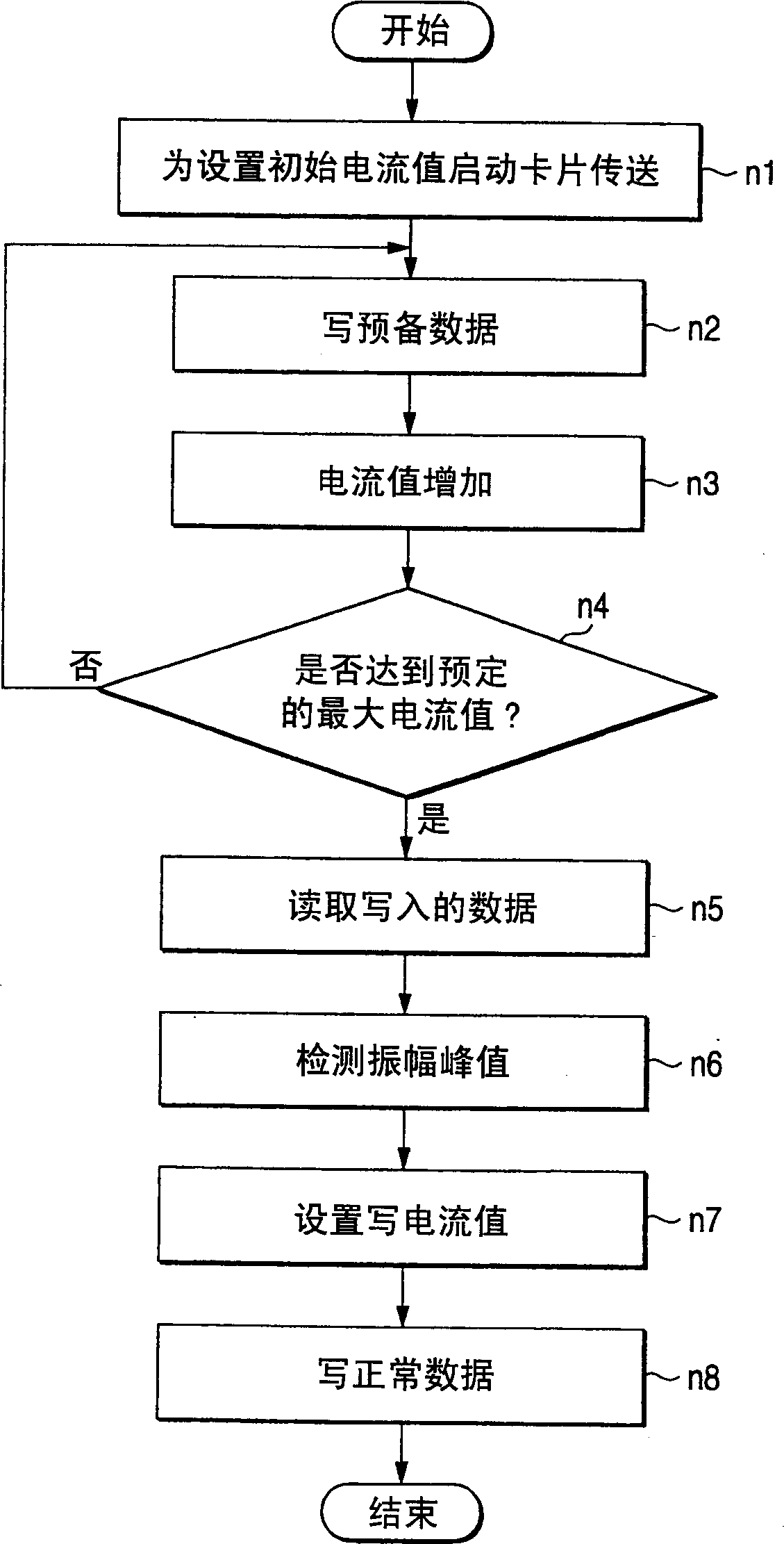

Image

  • Magnetic recording method and apparatus, device for determining coercive force of magnetic recording medium
  • Magnetic recording method and apparatus, device for determining coercive force of magnetic recording medium
  • Magnetic recording method and apparatus, device for determining coercive force of magnetic recording medium

Examples


no. 1 example

[0090] The figures show a card reader for writing information to and reading magnetic information from a magnetic card.

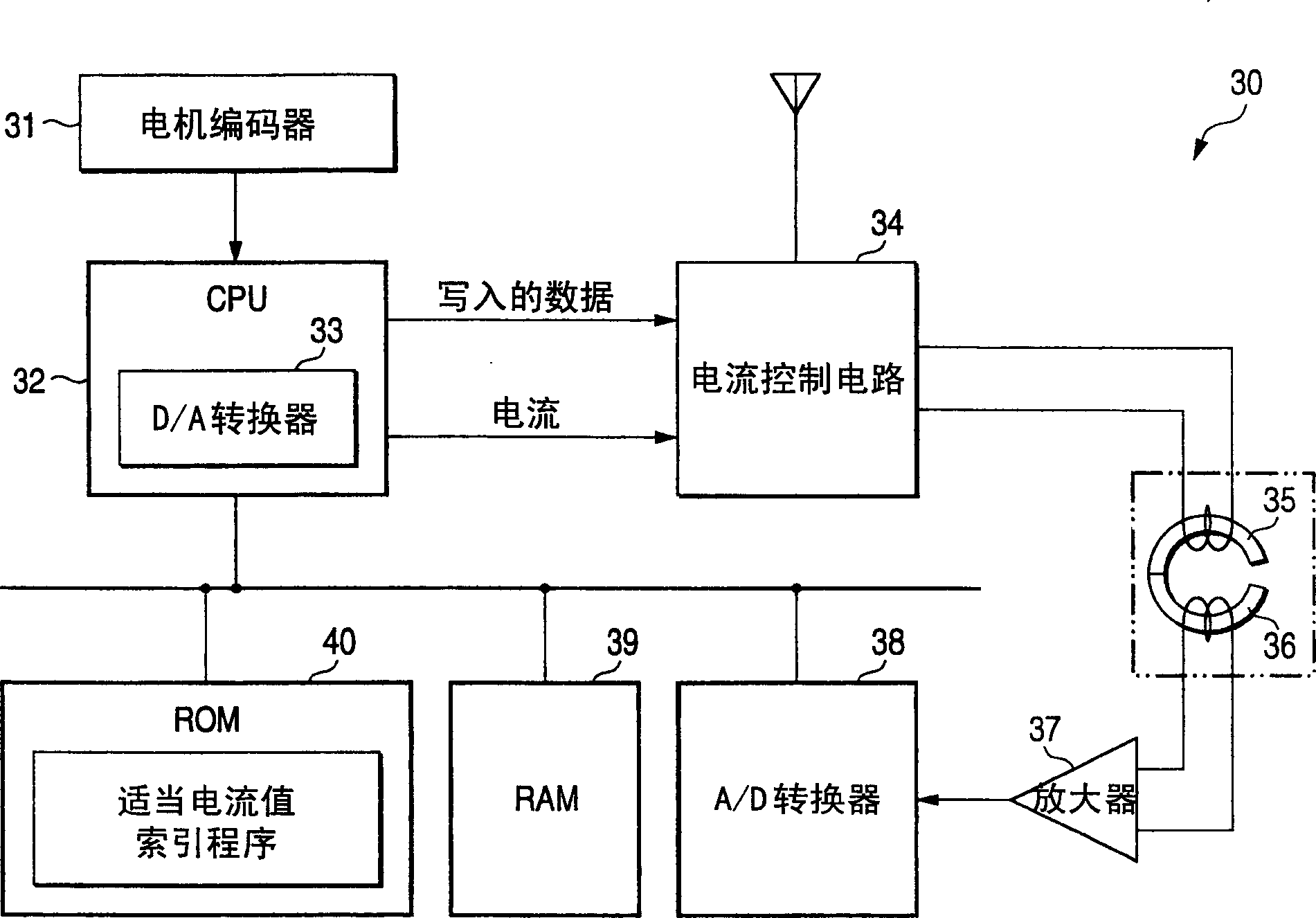
[0091] figure 1 A block diagram of the control circuit of the card reader 30 is shown. The card reader 30 has a motor encoder 31, a CPU 32, a D / A converter 33, a current control circuit 34, a write head 35, a read head 36, an amplifier 37, an A / D converter 38, a random access memory (RAM) 39 and the circuit structure of read-only memory (ROM) 40.

[0092] The motor encoder 31 is an encoder provided on the motor of the transmission system. When the motor rotates and outputs, the motor encoder 31 makes the photoelectric sensor detect the number of pulses through the slit on the disc on the motor shaft. Thus, the CPU 32 calculates the motor drive and the number of revolutions at that time.

[0093] The CPU 32 implements control processing of devices connected to the CPU 32 in accordance with programs stored in the ROM 40 . In the case where magnetic infor...

no. 2 example

[0123] Figure 5 A schematic cross-sectional view of a card reader 51 provided with means for determining the magnetic resistance of the magnetic card is shown.

[0124] The card reader 51 includes a card insertion opening 53 provided on the front surface of the main body 52, through which the magnetic card C is inserted or returned. The inside of the card reader 51 includes a card transport path 54 that allows the inserted magnetic card C to be transported forward and backward. The card transport path 54 is connected to the card insertion port.

[0125] Arranged around the card transport path 54 and extending deep inside from the card insertion port 53 are a pair of upper and lower forward transport rollers R1 and R2, a magnetic head 55, and a pair of upper and lower rear transport rollers R3 and R4. In addition, the first to third direction sensors S1 to S3 are arranged in three positions.

[0126] The rotation shafts of the vertically opposite conveying rollers among the...


PUM


Abstract

A method and apparatus are disclosed for determining an appropriate write current for a magnetic recording medium and to write magnetic information on the magnetic recording medium at the appropriate write current thus determined. When a current value suited to writing on a magnetic recording medium is to be found, a coercive force of the magnetic recording medium is found from a voltage at which magnetic information written on the magnetic recording medium is read, and a traveling quantity of the magnetic recording medium, and a current value corresponding to the coercive force, are found.

Description

technical field [0001] The present invention relates to a magnetic recording method, an apparatus thereof, and an apparatus for determining the coercive force of a magnetic recording medium, wherein in the magnetic recording method, magnetic information is recorded at an appropriate current value on a device such as a magnetic card, a form with a magnetic strip, or a magnetic ticket and other magnetic recording media. Background technique [0002] Generally, magnetic cards include two types of magnetic cards with different types of magnetic stripes. One is a low-coercivity magnetic card on which magnetic information is recorded by a magnetic head with a small write current. The other is a high-coercive magnetic card on which magnetic information is recorded by a magnetic head with a large write current. [0003] Sometimes, when the magnetic head writes the magnetic information to the low coercivity magnetic card with a large write current, the magnetic information cannot b...

Claims


Application Information

Patent Timeline
Patent Type & Authority Applications(China)
IPC IPC(8): G06K1/12G06K17/00G11B5/00G11B5/008
CPCG11B5/00808G06K1/125G06K17/00G11B2005/0013G11B2005/001
Inventor 守屋诚司芳井昌浩忠政明博堀之内健司濑崎学
Owner HITACHI OMRON TERMINAL SOLUTIONS CORP
Learn More