Lens optical shutter means

A shutter and lens technology, applied in shutters, optics, cameras, etc., can solve problems such as complex overall structure, complex maintenance, and complexity, and achieve the effect of simplifying the matching structure, simplifying the overall structure, and simplifying the relative relationship

Inactive Publication Date: 2004-03-10
OLYMPUS CORP
View PDF3 Cites 12 Cited by
  • Summary
  • Abstract
  • Description
  • Claims
  • Application Information

AI Technical Summary

Problems solved by technology

[0008] 1) Although the scheme of Japanese Patent Hei 4-44253 only uses one driving device to drive the two frames inside and outside, it seems to be simple in structure, but since it is necessary to make a motor to alternately drive the two frames to rotate, the additional device used But it is very complex, resulting in the complexity of its overall structure
[0009] 2) In this scheme, see image 3 and 4 As shown, the alternate driving by a motor is through the sliding fit relationship between the grooved pin 1b on the inner frame 1 and the arc-shaped groove 3b on the outer frame 3, and the two frames have toothed parts and toothless parts on their outer peripheral surfaces respectively. The matching relationship between the position and the stroke of the groove pin 1b in the arc-shaped groove 3b and the matching relationship between the size of the toothed part and the missing tooth part on the outer peripheral surface of the two frames. These three matching relationships can satisfy the conditions at the same time to make the motor Alternately drive the inner and outer frames to rotate. If any matching relationship does not meet the conditions, the entire device will not work. Therefore, this complex structure is very prone to failure during work.
[0010] 3) In this solution, due to the need for precise fit between the various parts, it has higher requirements on the shape of each part, and these parts also need higher dimensional accuracy to facilitate mutual cooperation, which increases the manufacturing cost. Difficulty machining these parts
For example, it is necessary to manufacture alternate shapes with teeth and missing teeth on the outer peripheral surfaces of the two frames, which itself is more complicated than manufacturing a full tooth shape, and it also requires the tooth shape dimensions between the two frames to match each other , which greatly increases the difficulty of manufacturing
[0011] 4) In this scheme, not only the manufacture is complicated, but also the maintenance in use is complicated, and the life of this structure is short
Because the two frames require the drive gear of the motor to start meshing with the teeth of the other frame when it is out of mesh with the teeth of one frame, and the end teeth of the teeth are most prone to wear, resulting in dimensional differences. Matched and unable to work, so even with frequent maintenance, its life is short
[0012] 5) In this scheme, there are unstable factors in the work of its aperture device
When the output gear of the motor turns from the state of meshing with the teeth of one frame to the state of meshing with the other frame, the frame that is out of mesh with the output gear is controlled by the ratchet spring to stand still, and the kinetic energy of the frame when it rotates at high speed large, and the kinetic energy is small at low speed rotation, so it is difficult to set the control force of the ratchet spring suitable for all speeds, and it is easy to cause failure

Method used


Image

  • Lens optical shutter means
  • Lens optical shutter means
  • Lens optical shutter means

Examples


Embodiment Construction

[0067] Embodiments of the present invention will be described below according to the accompanying drawings.

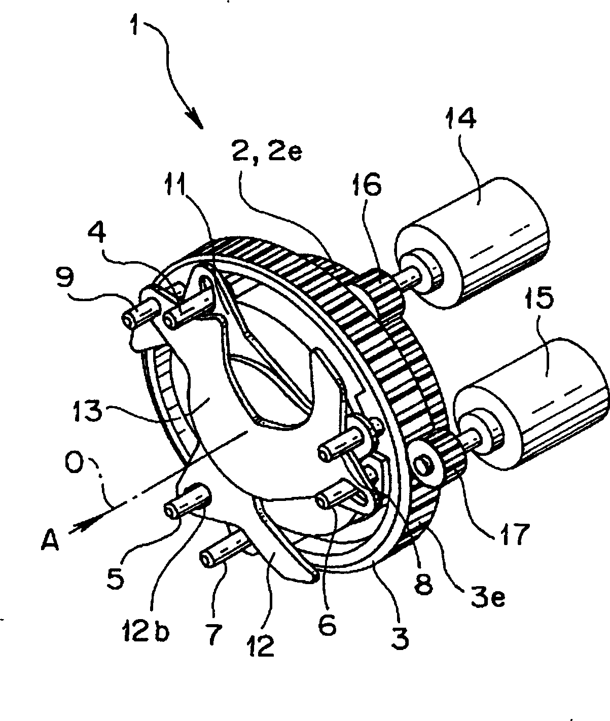
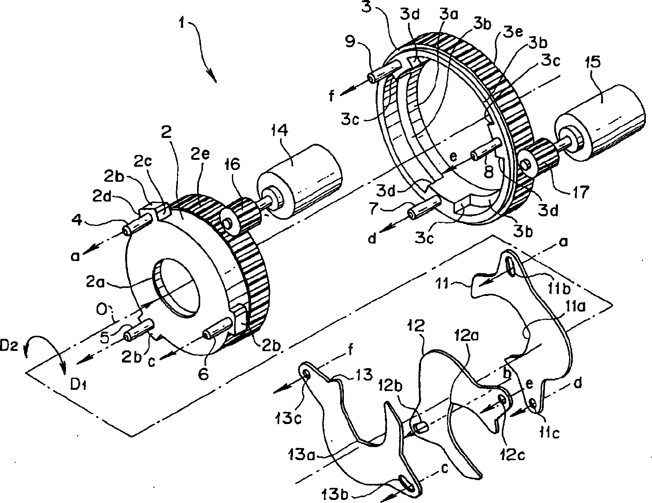
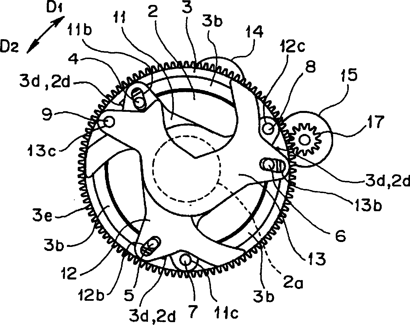
[0068] figure 1 It is a perspective view of the lens shutter device of the first embodiment of the present invention, figure 2 It is an exploded perspective view of the above-mentioned lens shutter device. Figure 3-8 Indicated by figure 1 The diagram of the opening and closing action state of the lens shutter device shown in the view of A, image 3 Indicates the fully closed state, Figure 4 express image 3 The halfway opening state after the state, or, to set the opening state, Figure 5 express Figure 4 state after the fully open state, Image 6 for Figure 5 The halfway opening state after the state, or, to set the opening state, Figure 7 express Image 6 The fully closed state after the state. Figure 8 This is a diagram showing the closed state of the shutter after setting the aperture. In addition, in the following description of each embodiment,...


PUM


Abstract

A lens shutter system has an inner drive ring which is rotated by a drive motor and an outer drive ring which is rotated by the drive motor. A plurality of shutter blades of the lens shutter system are driven through drive pins of the inner drive ring and drive pins of the outer drive ring so as to be opened and closed or are rotatably supported by the respective pins of the rings. Upon shutter opening, only the inner drive ring is driven clockwise to open the shutter blades. Upon shutter closing, only the outer drive ring is similarly driven clockwise to close the shutter blades. As mentioned above, upon switching between shutter opening mode and shutter closing mode, the direction of rotation of the inner and outer drive rings is not changed. Thus, the shutter operation can be performed at high speed.

Description

technical field [0001] The present invention relates to the structure of a lens shutter. Background technique [0002] In the case of conventional lens shutters, in the type suitable for adopting a set of fan-shaped parts for opening and closing drive, when the shutter is opened and closed, after the shutter is temporarily moved to the open position, it must be moved in the closing direction immediately. Perform reverse rotation drive. Therefore, it is difficult to quickly realize the opening and closing of the above-mentioned fan-shaped portions for the above-mentioned reverse rotation operation. [0003] As a type of increasing the speed of the above-mentioned conventional lens shutter, the lens shutter disclosed in JP Sho 45-26780 etc. suitably employs two sets of rotatable sectors of an opening sector and a closing sector. In this lens shutter, since when the shutter is opened and closed, the fan-shaped portion for opening and the fan-shaped portion for closing are res...

Claims


Application Information

Patent Timeline
Patent Type & Authority Applications(China)
IPC IPC(8): G03B9/10G03B9/08G03B9/22G03B9/24
Inventor 岩佐和行
Owner OLYMPUS CORP
Why Eureka
Try Eureka