
Circuit breakdown and oscillation identifying method based on resistance change rule

A resistance change, line fault technology, applied in the fault location, emergency protection circuit devices, electrical components and other directions, can solve the problems of incompatibility, numerical blindness, and difficulty in determining the predetermined value of the resistance change rate.

Active Publication Date: 2004-02-04
BEIJING SIFANG JIBAO AUTOMATION +1
View PDF0 Cites 11 Cited by
  • Summary
  • Abstract
  • Description
  • Claims
  • Application Information

AI Technical Summary

Problems solved by technology

[0009] The disadvantages of this method are: 1) The predetermined value (DRset) of the resistance change rate is difficult to determine
Generally, the simulation results of one model are used to replace all the line models, and its value has great blindness and inadaptability; 2) In oscillation, when a three-phase short circuit occurs, there are many cases where it cannot be achieved at all. When it is judged for the first time that the resistance change value ΔR1 is greater than 16 times the predetermined value of the resistance change rate, that is, the condition of "ΔR1>16*DRset" is not satisfied, so that the rapid distance 1 and 2 segments cannot be opened anymore

Method used


Image

  • Circuit breakdown and oscillation identifying method based on resistance change rule
  • Circuit breakdown and oscillation identifying method based on resistance change rule
  • Circuit breakdown and oscillation identifying method based on resistance change rule

Examples


Embodiment Construction

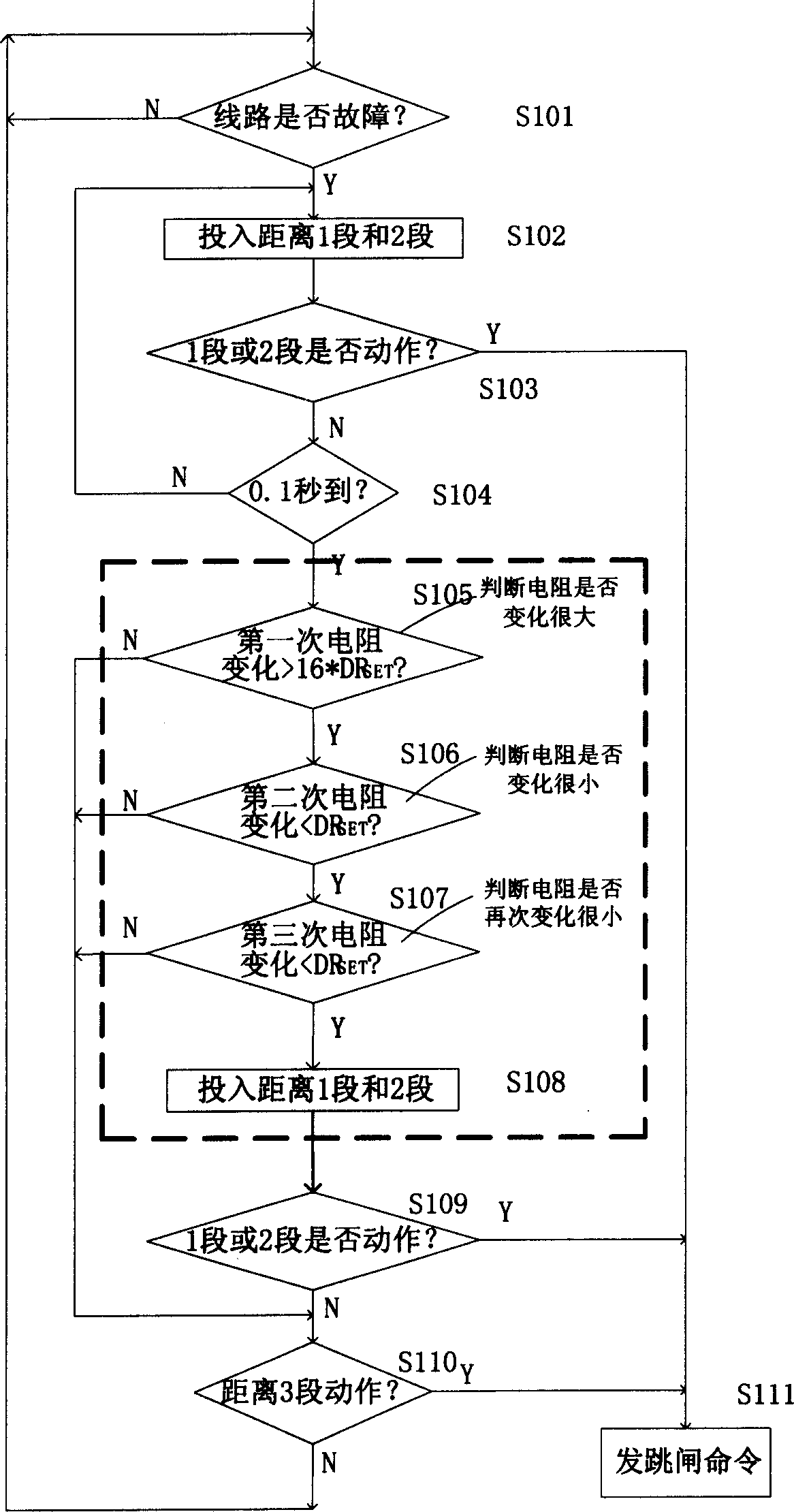
[0033] figure 1 It is a schematic flow chart of judging the resistance change rate in the prior art. Such as figure 1 As shown, firstly, starting from step S101, it is judged whether there is a fault in the line; if the judgment is negative, the loop monitoring is performed. If there is a fault, the flow process moves into step S102 and puts into distance 1 and 2, then enters step S103 to judge whether the distance 1 and 2 are active, and if the judgment is affirmative in step S103, then the flow proceeds to step S111 and sends a trip command; If the judgment in step S103 is negative, that is, there is no action for distance 1 and 2, then the process enters step S104 to determine whether 0.1 seconds is up, if the judgment is negative, then the process operation re-enters step S102, and input distance 1 and 2 2 paragraphs. If the judgment in step S104 is affirmative, that is, if it exceeds 0.1 second, then the flow process enters step S105 to judge whether the resistance cha...


PUM


Abstract

This invention opens a recognizing method basing on the circuit's failure and oscillation of resistance changing regularity, the method includes: judge whether the circuit has failure and whether distance 1 sect and 2 sect have action, if yes then send out jumping switch order; judge (after failure) whether it reach to 0.1 second, if over 0.1, second, then judge whether it is within the time sect tau, whether the resistance change is less than set-default of resistance changing rate DRset(tau), if in the tau time sect the resistance changing value is more than or equal Drset tau, than confirm as electricity system oscillation, thereby closedown easy misoperation (namly should not jump the switch, but take the switch jump out mistakenly, to broaden the power cut scale) distance protection, otherwise open the protection at all time, monitor whether the electricity system is failure, to ensure not having misoperation.

Description

technical field [0001] The invention relates to the field of power system automation, more specifically to a method for relay protection. technical background [0002] In the process of relay protection in power system automation, since the sensitivity of distance protection is not affected (or seldom) by the operation mode of the power system, and has a clear directionality, distance protection has been obtained on high-voltage transmission lines. Wide range of applications. In transmission lines with a voltage level of 110KV and above, distance protection is a must-have function for almost all transmission line protection equipment. However, when the power system oscillates, the distance protection will malfunction (that is, the power system does not fail, but the circuit breaker of the transmission line is tripped by mistake), resulting in the reduction of power transmission or accidents such as power outages. , which is an Achilles' heel of distance protection. [000...

Claims


Application Information

Patent Timeline
IPC IPC(8): G01R31/08H02H7/26
Inventor 黄少锋刘建飞秦应力张月品
Owner BEIJING SIFANG JIBAO AUTOMATION
Learn More