Mass center method for adjusting core making automatic end to end joint for wave-guide and optical fiber

An automatic docking and automatic adjustment technology, applied in the field of optical communication, can solve problems such as poor repeatability

Inactive Publication Date: 2003-12-24
UNIV OF SHANGHAI FOR SCI & TECH
View PDF2 Cites 15 Cited by
  • Summary
  • Abstract
  • Description
  • Claims
  • Application Information

AI Technical Summary

Problems solved by technology

[0003] The purpose of the present invention is to overcome the shortcomings of poor repeatability of existing conventional alignment, and to provide a new automatic alignment method, which avoids directly searching for the peak position, and uses the centroid of the coupling efficiency distribution near the measured peak To determine the peak position, it overcomes the difficulty that the conventional alignment process depends on the accurate test of the micro-variation signal in principle

Method used

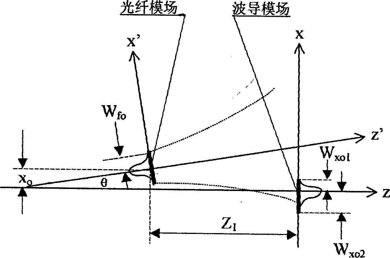
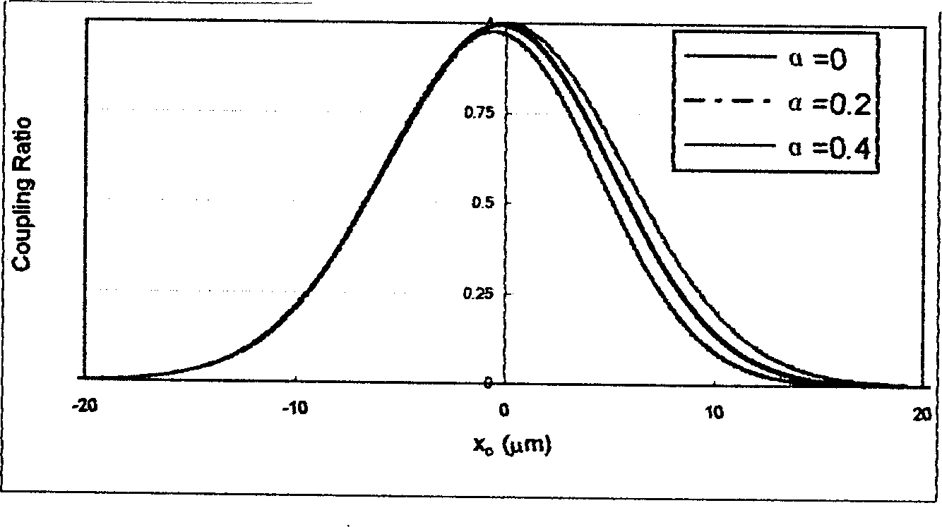
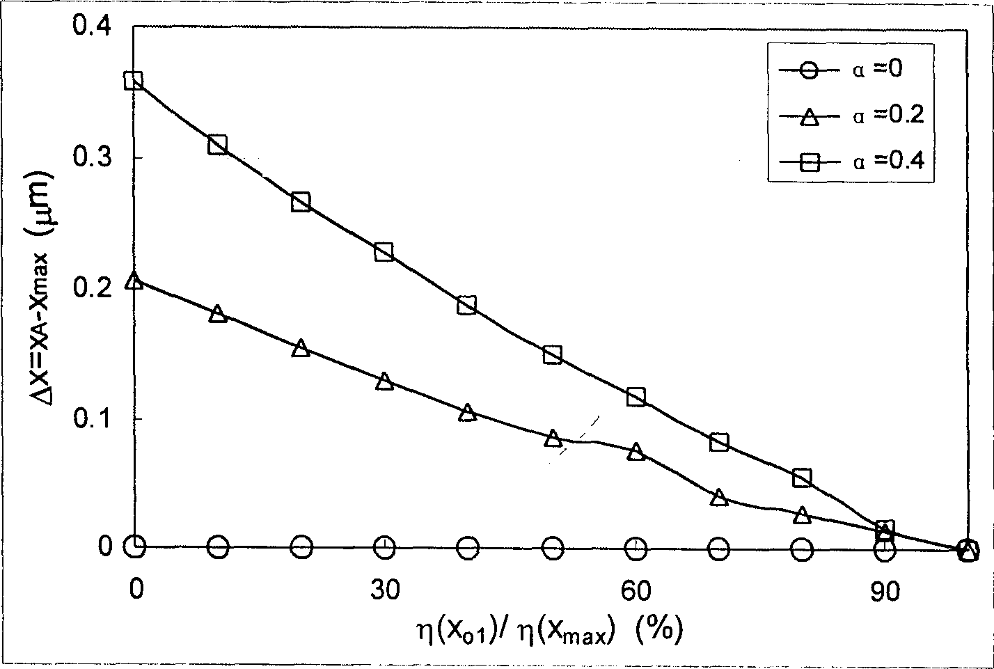

Image

  • Mass center method for adjusting core making automatic end to end joint for wave-guide and optical fiber
  • Mass center method for adjusting core making automatic end to end joint for wave-guide and optical fiber
  • Mass center method for adjusting core making automatic end to end joint for wave-guide and optical fiber

Examples


Embodiment 1

[0053] Optical fiber - automatic core adjustment of optical fiber and its results:

[0054] A commercially available flat-polished single-mode fiber patch cord was used as the standard waveguide in the experiment. Since the mode field distribution of single-mode fibers is very standardized, the coupling test between single-mode fibers can eliminate the influence of waveguide defects and objectively reflect the characteristics of the software and hardware of the core alignment system. Install two single-mode optical fibers with clean and dry end faces on the bracket of the core alignment instrument, and place a small amount of refractive index matching liquid between the end faces of the two optical fibers. The refractive index of the matching liquid is 1.445 and 1.444 at wavelengths of 1310nm and 1550nm, respectively. The refractive index difference with the silica fiber core is less than 0.01, and the reflection loss is less than -50dB. The transmittances of the matching liq...

Embodiment 2

[0058] Fiber-waveguide-fiber automatic core alignment and its results:

[0059] The optical waveguide uses quartz-based SiO produced by NHK Corporation of Japan 2 Buried single-mode strip waveguide, the design value of the waveguide core section size is 8×8μm 2 , The relative refractive index difference Δ = 0.3%, both ends of the plane grinding. The input and output ends are respectively connected to single-mode optical fibers, and a refractive index matching liquid is arranged between the end faces. The rough adjustment process is basically the same as the fiber-to-fiber one above. Since there is a pair of couplings at both ends of the waveguide, the initial light adjustment is easy to judge by using 632.8nm visible light. After the light is passed between the fiber-waveguide-fiber, the feedback channel between the computer and the power meter enters the operational state, and at this time, the input light is changed to near-infrared light. The automatic alignment at both ...


PUM


Abstract

A centroidal centralizing method for automatic butt coupling between waveguide and optical fibre features that the peak position can be determined by measuring the calculating the mass center near the peak, and includes initializing, coarse steps, fine steps, integration to find mass center, and repeating said steps for finding out the mass center of another dimension. Its equipment is composed of voltage-stabilized power supply, heat-stability light source, two sets of 6D precise regulator, regulator for fixing waveguide, drive controller of step motor, microscopic photography and observing system, high-resolution optical powermeter, and computer.

Description

technical field [0001] The invention relates to a waveguide-fiber automatic docking and center-of-mass core-adjusting method for the automatic connection and packaging technology of an integrated optical waveguide device and a single-mode optical fiber, which belongs to the field of optical communication. Background technique [0002] Because optical waveguide devices have the advantages of small size, high functional integration, and suitable for mass production, in recent years, in the Tbit / s ultra-high-speed transmission experiment of the optical communication backbone network and the fiber-to-the-home technology of the access network, more and more More and more optical waveguide devices are used. To introduce optical waveguide devices into optical fiber networks, the first problem that must be solved is the connection and packaging of optical brazing and optical waveguides. Considering the direct impact of device insertion loss on network economy, one of the key techno...

Claims


Application Information

Patent Timeline
IPC IPC(8): G02B6/38H04B10/25
Inventor 陈抱雪龙彩华沙慧军
Owner UNIV OF SHANGHAI FOR SCI & TECH
Why Eureka
Try Eureka