
Electrodynamic field generator

A generator and force field technology, applied in the field of rotary DC generators, can solve problems such as local driving force difference

Inactive Publication Date: 2003-12-17
马克·R·托米奥恩
View PDF6 Cites 18 Cited by
  • Summary
  • Abstract
  • Description
  • Claims
  • Application Information

AI Technical Summary

Problems solved by technology

In addition, the device also addresses the problem of, for the purpose of maneuvering flight and / or controlling direction, by providing a number of pulsed discharge propulsion units arranged in concentric rings (inside the disk) and having independent diffuse nozzles, in A local difference in driving force is produced on the body or casing of such a device
Finally, none of the above related prior art devices has developed a thrust-generating electrodynamic field like the present invention, which can achieve multiple target functions, such as the generation of useful thermal kinetic energy and the development of potential energy signal communication capabilities

Method used


Image

  • Electrodynamic field generator
  • Electrodynamic field generator
  • Electrodynamic field generator

Examples


Embodiment Construction

[0034] Description of the preferred embodiment

[0035] Operating principle:

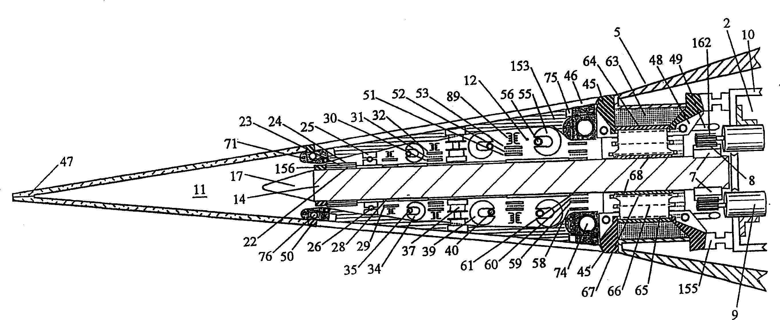
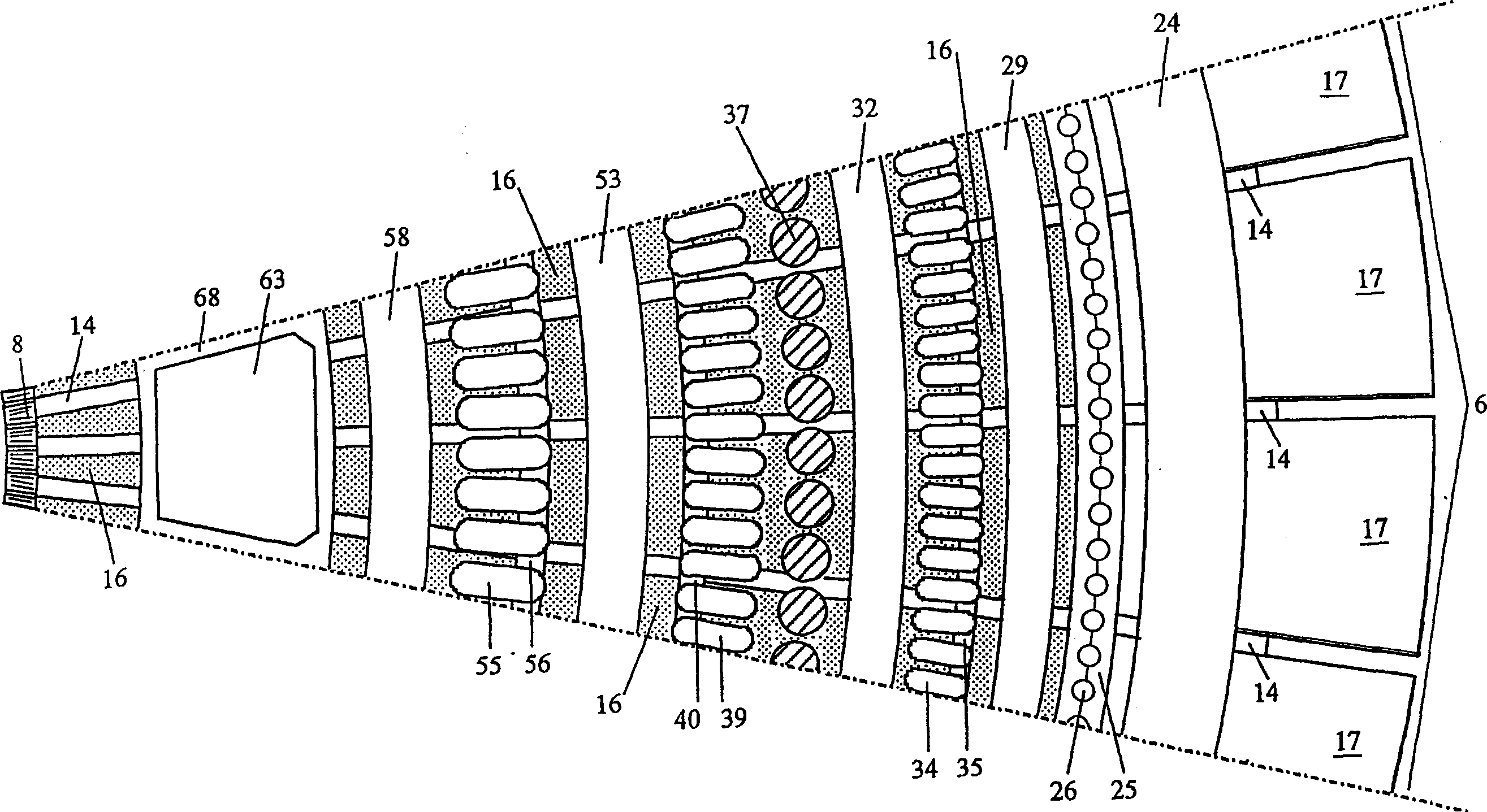
[0036] The invention described herein is an Electrodynamic Field ("EDF") generator. Crucial to the achievement of the objects of the present invention is how to create and maintain a megavolt potential difference across the outer region of the enclosure so that the potential difference is not immediately neutralized by uncontrolled direct arcing. The first problem is that it is impossible to generate this voltage directly in a conventional coil, so the voltage applied to the charged enclosure area must be obtained through a special electrostatic device. Second, the discharge current must be generated and conducted internally in the following manner: (1) only a small fraction of the discharge current is actually conducted by the coil (within a very limited ampacity compared to the rotor); The charging process of the positive and negative regions is faster than the discharging process, until a large...


PUM


Abstract

This device is a brushless high-voltage electrical generator for producing a high energy external electrodynamic field or continuous quasi-coherent DC corona or arcdischarge of uniformed current density which completely encloses the machine's conductive housing (1). This housing is divided into distinct electrical sections (3-5) and contains a flat conductive rotor (6) electrically links separate negative (3) and positive (5) housing sections and upon which a plurality of toroidal generating coils (35, 40, 56) are rotatably mounted. Circular arrays of stationary permanent magnets (34, 39, 55) are affixed within the housing which induce a constant DC voltage within said coils upon their rotation. The primary voltage generated is electrostatically impressed across the rotor such that great quantities of electronic charge may be transported between the opposite polarity sections (3-5) of the housing, in such a manner that a much higher secondary voltage is caused to appear across interposed neutral sections thereof, and the resulting external breakdown current once initiated is independent of the generating coils'ampacity. Ancillary mechanical, electrical, and / or electronic features may be attached upon or within the housing to aid in harnessing and controlling the useful effects associated with the external dynamic electric field produced by the device.

Description

technical field [0001] The present invention relates generally to rotating direct current generators incorporating permanent magnetic fields, and more specifically to devices similar to electromechanical generators, the primary purpose of which is to generate a useful continuous high voltage direct current corona discharge. The present invention also relates to space vehicles capable of utilizing the propulsion produced by a particular type or form of ultra-high voltage corona or arc discharge. Background technique [0002] In order to fully understand the present invention and understand the context, it is necessary to provide background materials, and some related prior art patents are listed as references in the following text. These cited references have some similarities to the present invention, mainly related to the purpose of how to generate electrogenic driving force. However, the means to achieve this goal have obvious differences and limitations. [0003] The re...

Claims


Application Information

Patent Timeline
Patent Type & Authority Applications(China)
IPC IPC(8): H05H1/54B64C39/00H02K21/28H02N11/00H05H1/24
CPCH02N11/006B64C39/001H05H1/24H05H1/47H01J37/32339
Inventor 马克·R·托米奥恩
Owner 马克·R·托米奥恩
Learn More