Reciprocating movement compressor

A reciprocating motion and compressor technology, which is applied in the field of compressors, can solve problems such as impact, lubricating oil suction cannot be carried out smoothly, and increased oil circuit resistance

Inactive Publication Date: 2003-11-26
LG ELECTRONICS (TIANJIN) APPLIANCES CO LTD
View PDF0 Cites 5 Cited by
  • Summary
  • Abstract
  • Description
  • Claims
  • Application Information

AI Technical Summary

Problems solved by technology

[0014] Since various foreign substances generated during the assembly of the compressor and during the driving of the compressor are deposited in the lubricating oil and sucked together with the lubricating oil when it is drawn out, problems such as abrasion of the sliding part of the compression part (30) may occur, causing serious problems. The quality and reliability of the compressor have adverse effects
[0015] In addition, since the lubricating oil suction pipe 61f of the lubricating oil supply part 60 formed by bending at a right angle increases the oil passage resistance when lubricating oil is sucked in, so the lubricating oil cannot be sucked in smoothly.
[0016] This shows that there are still many defects in the above-mentioned existing reciprocating compressor, and it needs to be improved.

Method used


Image

  • Reciprocating movement compressor
  • Reciprocating movement compressor
  • Reciprocating movement compressor

Examples


Embodiment Construction

[0037] Below in conjunction with the accompanying drawings and preferred embodiments, the specific implementation, structure, features and effects of the present invention will be described in detail as follows.

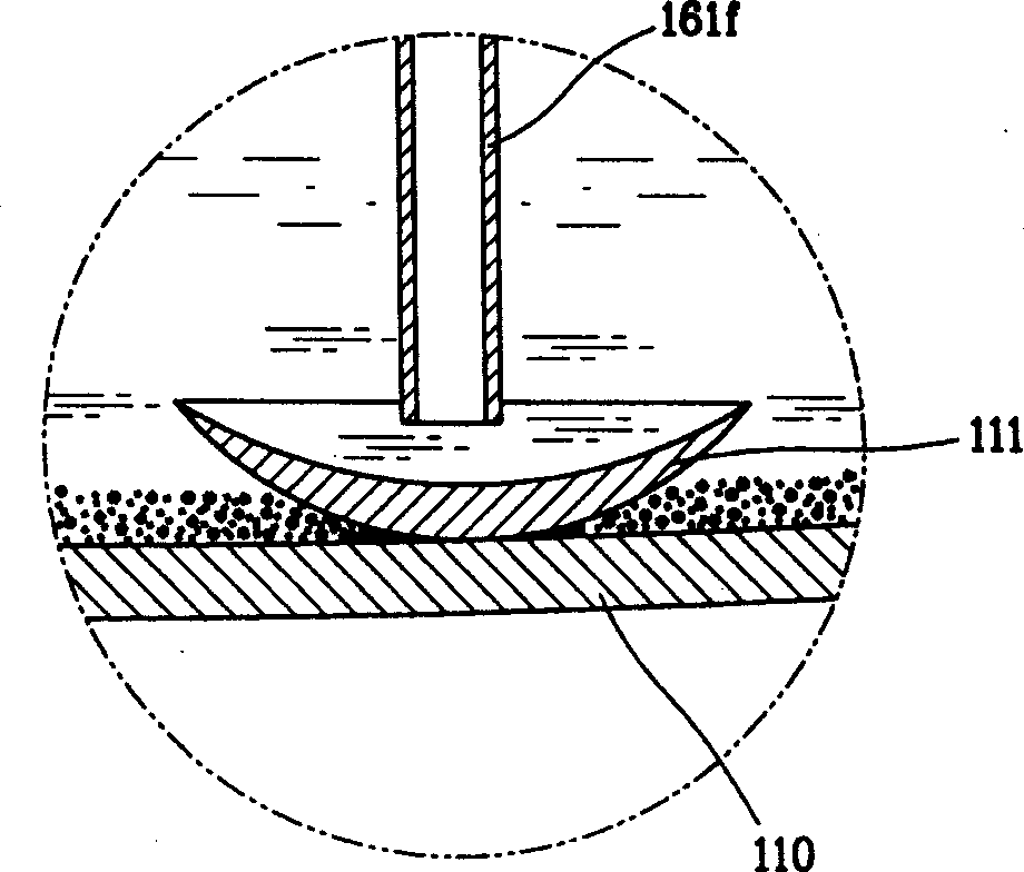
[0038] 110. Airtight container 111. Shielding part

[0039] 120. Reciprocating motor 121. Stator

[0040] 122. Rotor 130. Compression part

[0041] 140. Frame part 150. Spring part

[0042] 160. Lubricating oil supply department 161. Lubricating oil pumping department

[0043] 162. Lubricating oil supply flow path 161f. Lubricating oil suction pipe

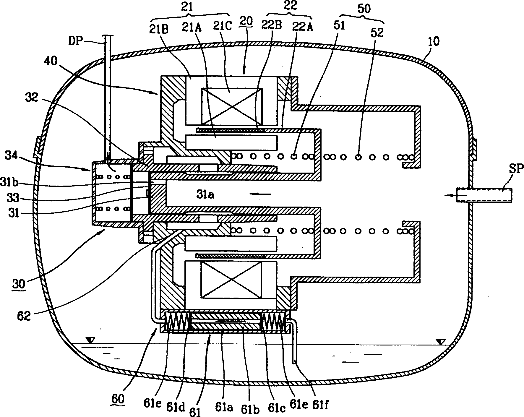
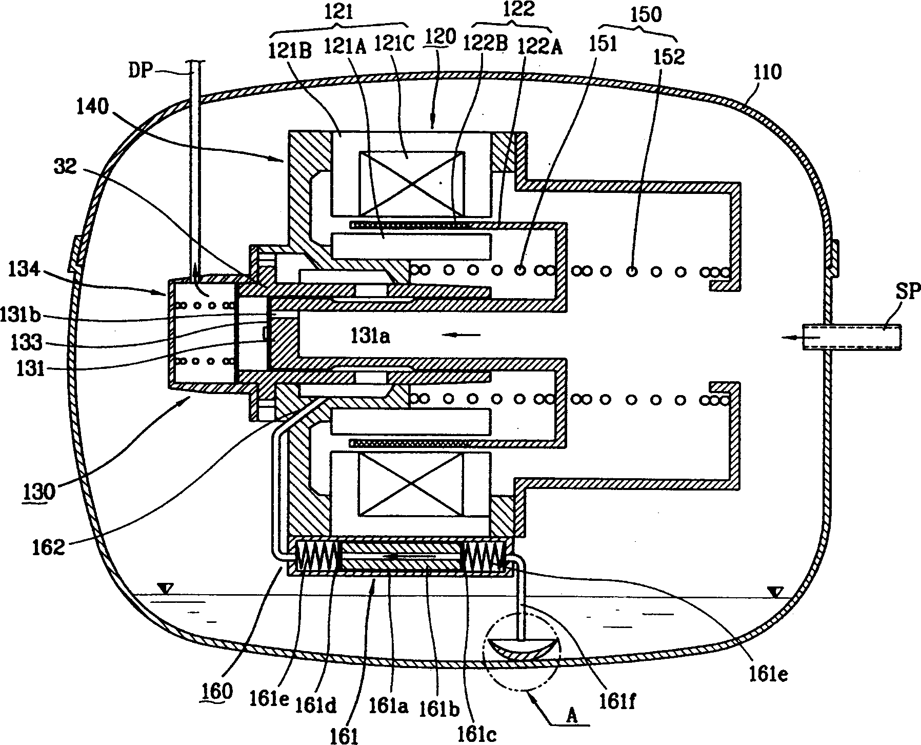
[0044] see figure 2 , image 3 , Figure 4 As shown, the reciprocating compressor of the present invention has the following structure: the reciprocating motor 120 is arranged inside the airtight container 110 with a certain amount of lubricating oil, and the frame 40 supports the compression part 130 combined with the reciprocating motor 120; The oil supply unit 160 is attached to the frame unit 140 , and supplies...


PUM


Abstract

The reciprocating motion compressor includes sealed container, reciprocating motor, frame, compressor, and lubricant oil supplying assembly. The sealed container has lubricating oil inside the bottom, the frame is supported elastically inside the sealed container, and the lubricant oil supplying assembly supplies the compressor with lubricating oil and consists of lubricating oil cylinder vibrating together with the frame, lubricating oil piston inserted inside the lubricating oil cylinder to slide and pump out lubricating oil and lubricating oil sucking pipe. The baffling part inside the sealed container stops the foreign matter deposited in the lubricating oil inside the sealed container from being sucked to the lubricant oil supplying assembly and the compressor, and this can avoid wear of the compressor and raise the quality and reliability of the reciprocating motion compressor.

Description

technical field [0001] The present invention relates to a compressor, in particular to a reciprocating compressor which can not only prevent the inhalation of foreign matter, but also make the inhalation of lubricating oil smooth. Background technique [0002] Generally, reciprocating compressors are generally divided into two types. One is to convert the rotary motion of the driving motor into the reciprocating motion of the piston to compress and discharge the inhaled gas; the other is to convert the linear reciprocating motion of the driving motor into the reciprocating motion of the piston to compress and discharge the inhaled gas. [0003] figure 1 It is a sectional view of a prior art reciprocating compressor. [0004] Such as figure 1 As shown, the prior art reciprocating compressor includes the following structures: a closed container 10 , a reciprocating motor 20 , a compression part 30 , a frame part 40 , a spring part 50 and a lubricating oil supply part 60 . ...

Claims


Application Information

Patent Timeline
IPC IPC(8): F04B35/04F04B39/02
Inventor 徐钟太裵圭锺金长焕
Owner LG ELECTRONICS (TIANJIN) APPLIANCES CO LTD
Why Eureka
Try Eureka