Cutting tool capable of changing knife head and knife head capable of installing on said cutting tool

A cutting tool and replaceable technology, which is applied in the direction of manufacturing tools, accessories of tool holders, and tools used in lathes, etc., can solve the problems of the cutting head falling off, the rigidity cannot be guaranteed, and the installation state of the cutting head is poor. Stability, increased rigidity, and the effect of maintaining a stable installation state

Inactive Publication Date: 2003-09-17
MITSUBISHI MATERIALS CORP
View PDF3 Cites 13 Cited by
  • Summary
  • Abstract
  • Description
  • Claims
  • Application Information

AI Technical Summary

Problems solved by technology

[0030] However, such a cutting tool with a replaceable bit has a problem that the relative rotation of the bit and the bolt portion in the circumferential direction is not prevented, not only during the bit mounting work, but also when the bit is installed. After being attached to the tool body, when the bit is subjected to a force in the circumferential direction, the bit may easily fall off from the bolt, and the installation state of the bit is extremely poor.
[0031] In addition, the shaft portion of the snap joint is simply formed in a roughly cylindrical shape, so there is still a problem that its rigidity cannot be guaranteed.

Method used


Image

  • Cutting tool capable of changing knife head and knife head capable of installing on said cutting tool
  • Cutting tool capable of changing knife head and knife head capable of installing on said cutting tool
  • Cutting tool capable of changing knife head and knife head capable of installing on said cutting tool

Examples


Embodiment Construction

[0097]Hereinafter, embodiments of the present invention will be described with reference to the accompanying drawings.

[0098] First, a first embodiment of the present invention will be described.

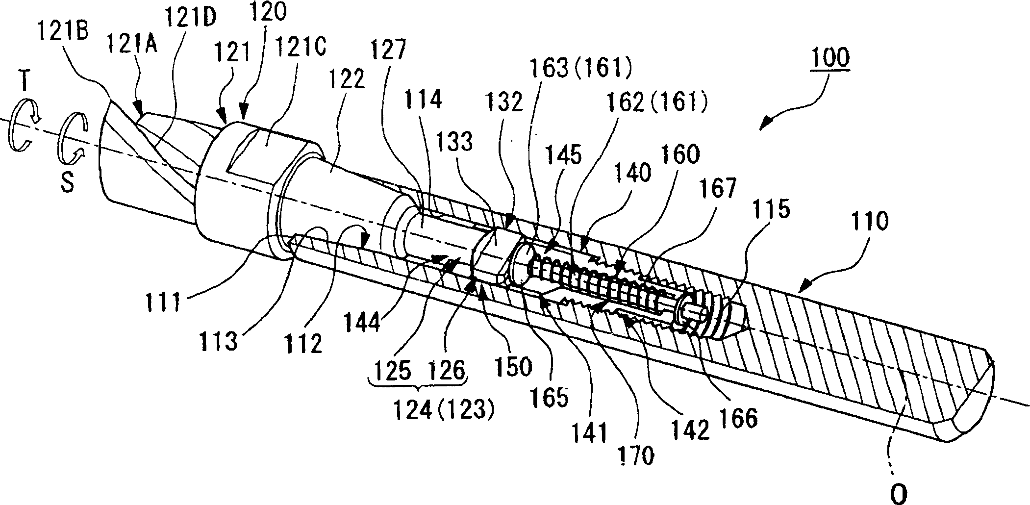
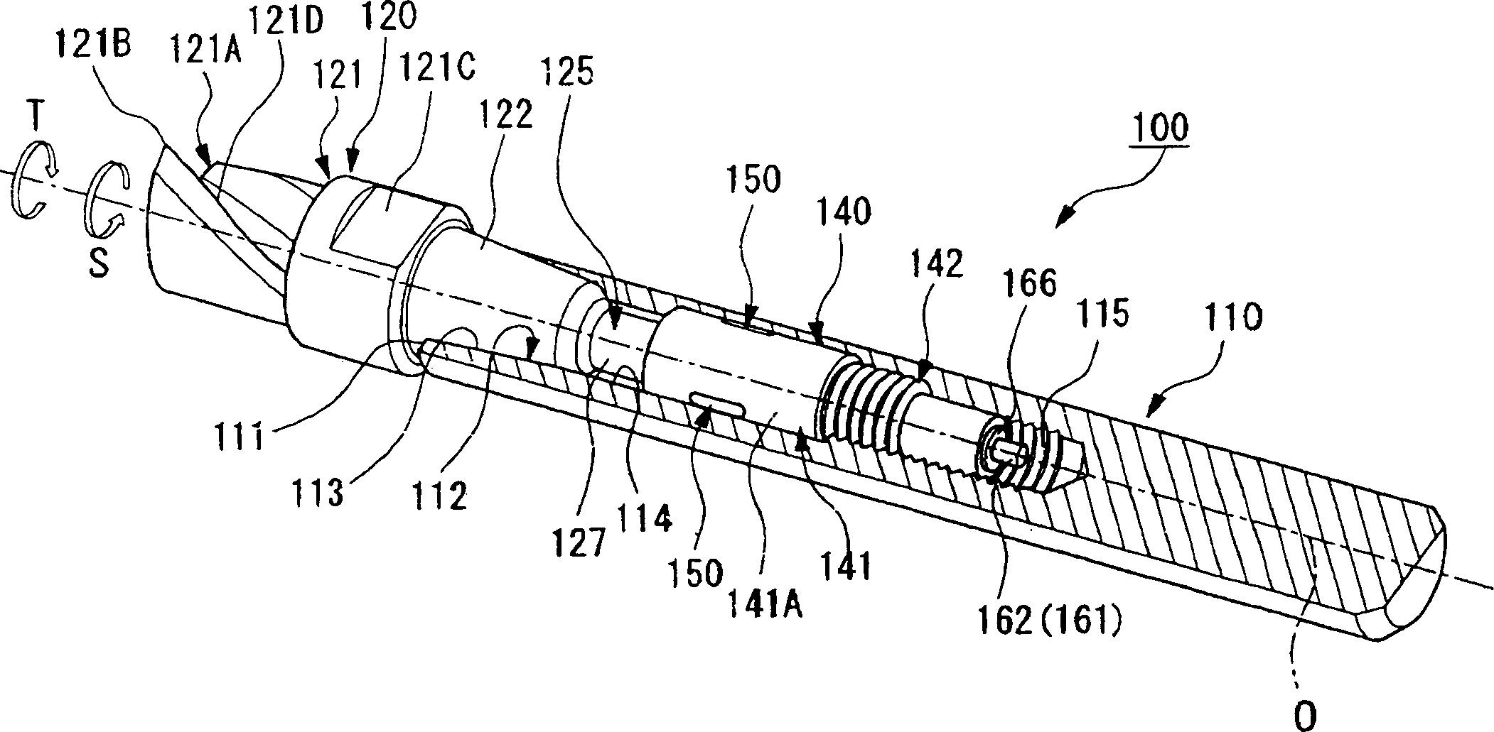
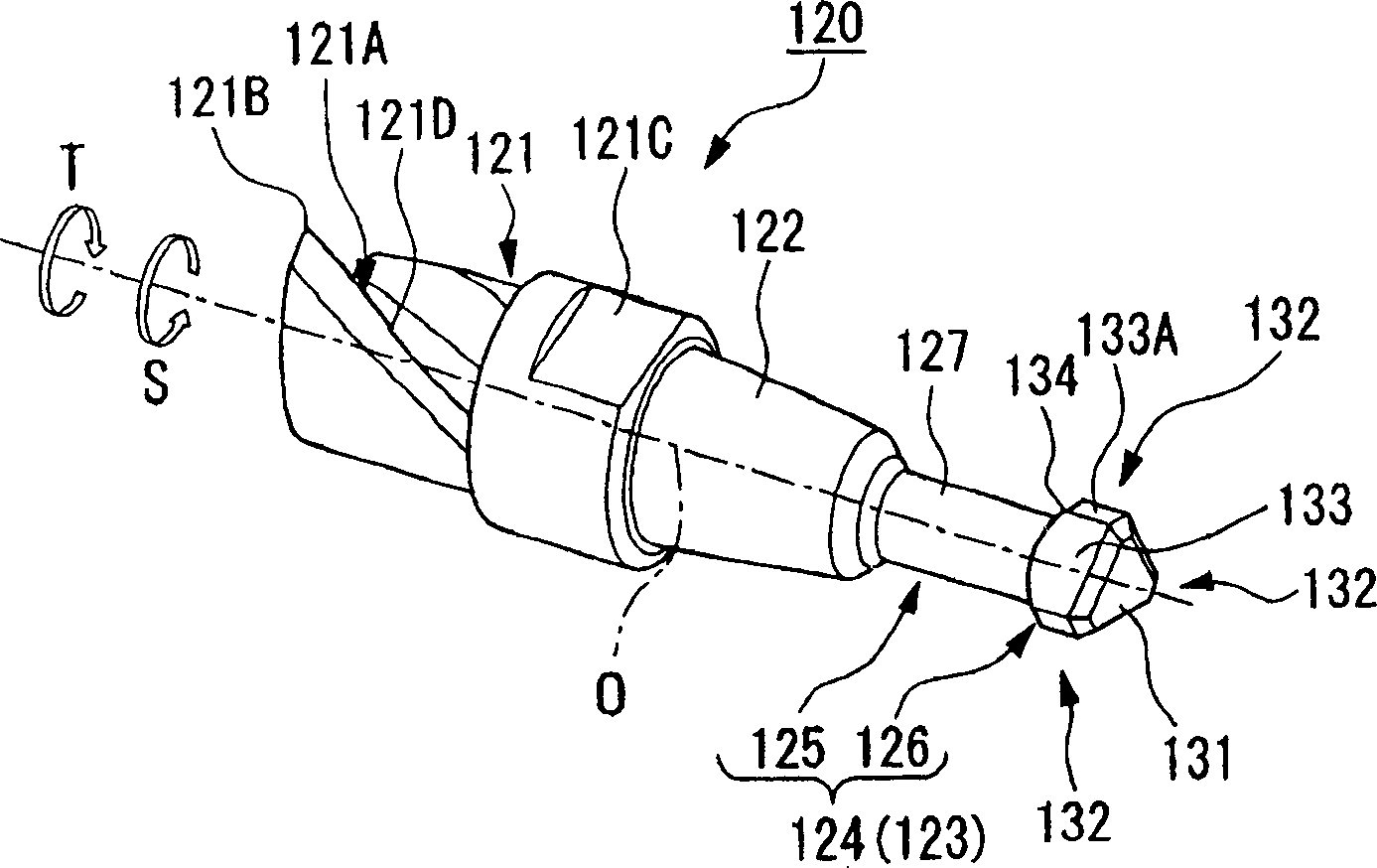
[0099] The cutter head replaceable cutting tool 100 provided by this first embodiment is as figure 1 and figure 2 As shown, a tool body 110 that can rotate around the axis O, a cutter head 120 that is detachably mounted and fixed on the tool body 110 , and a pull-in tool for installing the cutter head 120 on the tool body 110 The bolt portion 140 of the component constitutes.

[0100] The tool body 110 is, for example, made of steel and has a substantially cylindrical shape centered on the axis O, and has a mounting hole 112 centered on the axis O from the front end surface 111 toward the rear end side.

[0101] The mounting hole 112 is composed of a conical hole 113, an accommodating hole 114 and a female thread portion 115; wherein, the inner diameter of the conical hole 11...


PUM


Abstract

Eccentricity is not allowed to occur in a blade section, and a blade section is maintained in a stable installation state. A hook section 124, which is composed of a shaft section 125 and an end section 126 provided with a corner section 132 that protrudes as a ledge farther to the outside in the radial direction than this shaft section 125, is formed in a blade section 120. A hook hole 144, which allows the passage of end section 126 of hook section 124, is formed in a bolt section 140. Engaging sections 150 are formed around hook hole 144. Corner sections 132 of end section 126 of hook section 124 are engaged with engaging sections 150 when blade section 120 and bolt section 140 are relatively moved in the direction in which they move away from each other in the direction of an axis O in the state in which blade section 120 is rotated by about 60 DEG towards the front in a direction of screwing rotation S with respect to bolt section 140 after inserting and passing end section 126 of hook section 124 through hook hole 144. <IMAGE>

Description

technical field [0001] The invention relates to a replaceable cutting tool with the cutter head detachably installed on the tool body. Background technique [0002] In the past, as such a bit-replaceable cutting tool, there is an example in which both the rear end portion of the bit having a cutting portion having at least one cutting edge and the front end portion of a bolt portion having a male thread Removably connected together, insert these connected cutter heads and bolts into the mounting holes with female threads on the tool body, and screw the male threads of the bolts into the female threads of the mounting holes part, the bit is drawn into the rear end side of the tool body in the axial direction, thereby being detachably mounted on the tool body. [0003] For example, there is a tip replaceable cutting tool 10 disclosed in Patent Document 1 shown in FIG. The snap joint 24 formed by the groove 22 of the opening and the tongue portion 23 partially cuts off the ou...

Claims


Application Information

Patent Timeline
Patent Type & Authority Applications(China)
IPC IPC(8): B23Q3/12B23B31/06B23B31/107B23B31/11B23B31/113B23C5/26
CPCB23B31/06B23B31/1076B23B31/1107B23B31/1122B23B31/113Y10T409/30952Y10T408/957Y10T409/309408Y10T409/309352Y10T279/17863Y10T409/309464B23B27/16
Inventor 木村良彦中村彻阿部太郎佐藤隆广
Owner MITSUBISHI MATERIALS CORP
Why Eureka
Try Eureka