Tiltmeter

A technology of tilt detector and fixed contact, applied in the direction of measuring tilt, instruments, measuring devices, etc., can solve the problems of low detection accuracy and unstable contact.

Inactive Publication Date: 2003-08-20
ALPS ALPINE CO LTD
View PDF0 Cites 5 Cited by
  • Summary
  • Abstract
  • Description
  • Claims
  • Application Information

AI Technical Summary

Problems solved by technology

[0007] However, in the structure of the above-mentioned conventional tilt detector, the above-mentioned first fixed contacts 12a, 12b and the second fixed contacts 13a, 13b are provided on the above-mentioned in...

Method used


Image

  • Tiltmeter
  • Tiltmeter
  • Tiltmeter

Examples


Embodiment Construction

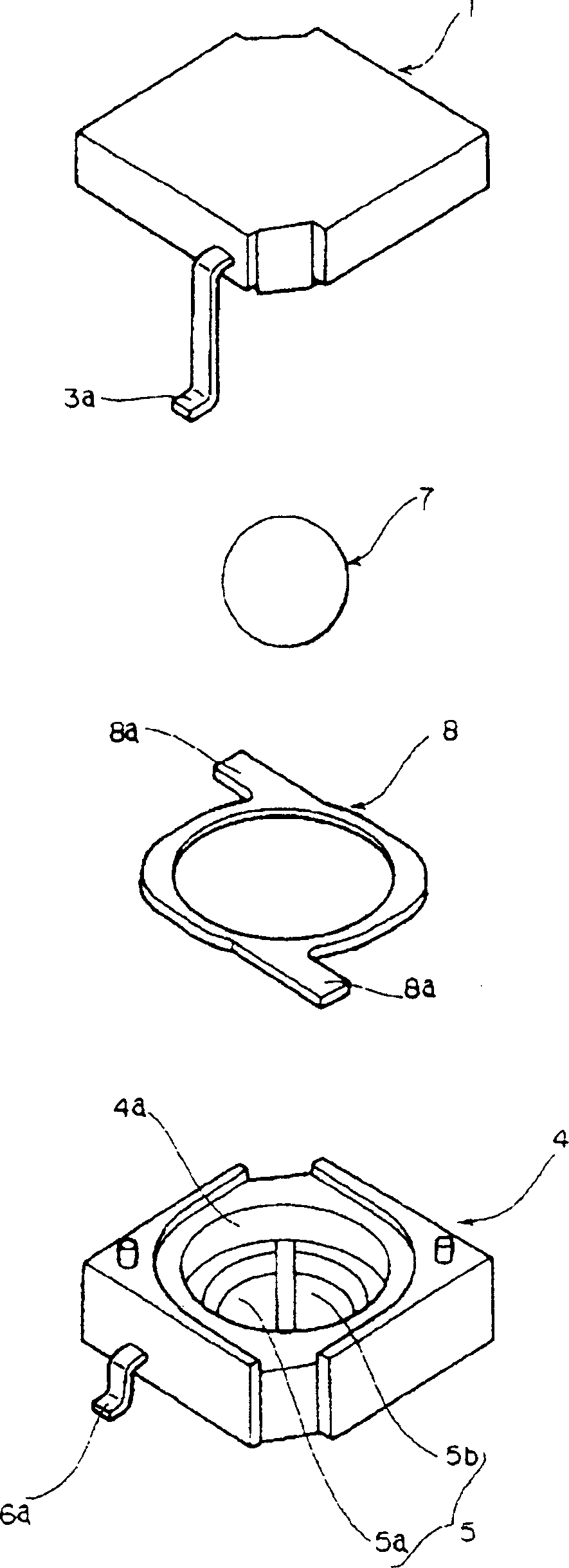
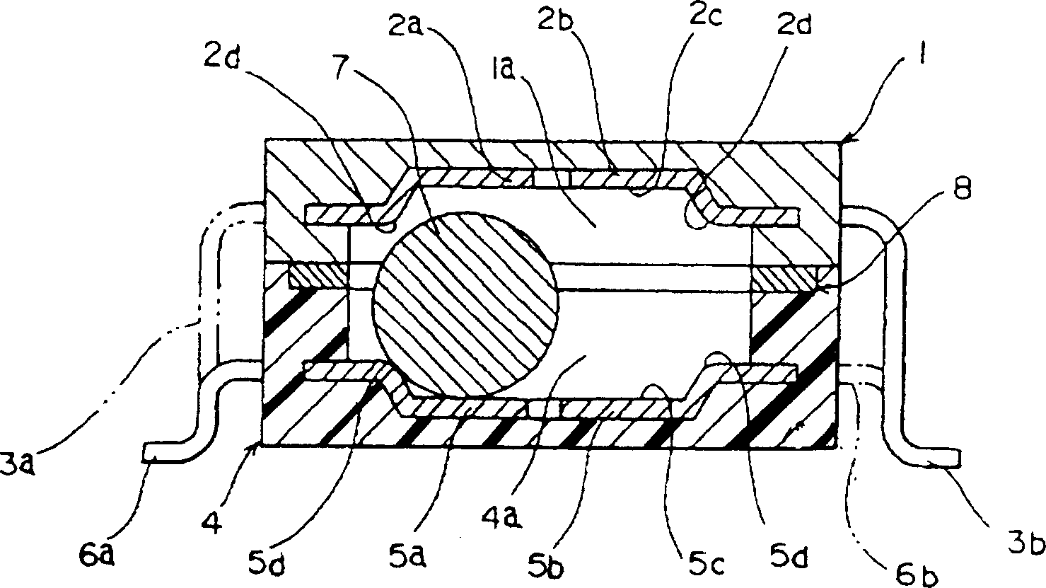
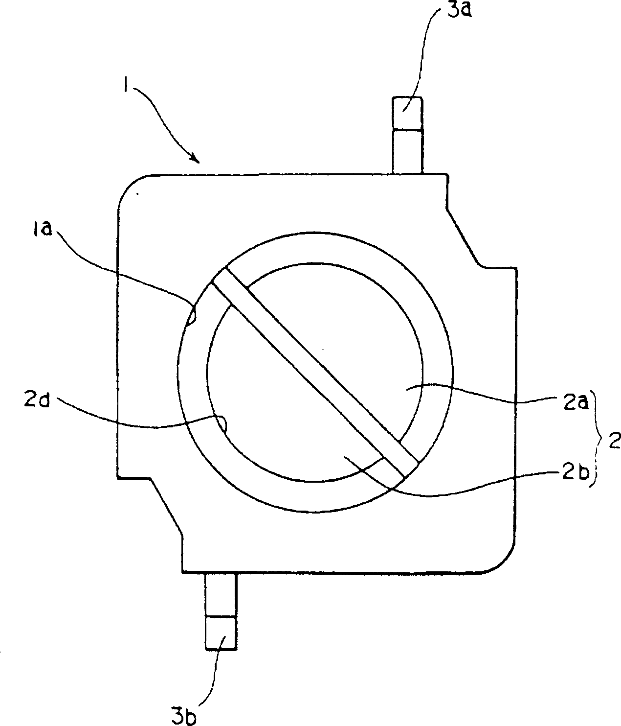
[0023] the following Figure 1 to Figure 7 Embodiments of the present invention are shown. figure 1 is the exploded oblique view of the tilt detector, figure 2 is a longitudinal section view, image 3 is the bottom view of the first case, Figure 4 is the plan view of the second case, Figure 5 It is an explanatory diagram showing the operating state of the movable contact when tilted to the left, Figure 6 It is an explanatory diagram showing the operating state of the movable contact when tilting to the right, Figure 7 It is a longitudinal sectional view showing another embodiment.

[0024] In the figure, the first housing 1 is made of an insulating material such as synthetic resin and is formed into a box shape with an open bottom. In the opening of the first case 1, a bottomed and circular first housing portion 1a is formed, and on the inner bottom surface of the first housing portion 1a, a first housing made of a conductive metal plate is provided almost on the e...


PUM


Abstract

A spherical movable contact is housed in housing portions of a first case and a second case so as to be able to roll, and is to come into or go out of contact with a first fixed contact and a second fixed contact. The first case and the second case are fixed to each other so as to form an integral body in such a manner that the first fixed contact and the second fixed contact are opposed to each other. At least one of the first fixed contact and the second fixed contact is divided. The movable contact is disposed so as to roll while bridging the first fixed contact and the second fixed contact. Contact portions where the movable contact is to contact the first fixed contact and the second fixed contact assume arc shapes, respectively.

Description

technical field [0001] The present invention relates to the structure of a tilt detector used in products having a direction detection function used in various portable electronic devices, home game machines, toys, and the like. Background technique [0002] The structure of the existing tilt detector is shown in Figure 8 ~ Figure 10 . Figure 8 is the exploded oblique view of the tilt detector, Figure 9 It is a longitudinal sectional view viewed from the side, Figure 10 It is an explanatory diagram showing the operating state of the spherical movable contact. [0003] As shown in the figure, the components of the existing tilt detector include: an insulating substrate 11, which is made of insulating material; first fixed contacts 12a, 12b, which are made of conductive metal plates, and are arranged side by side on the above-mentioned On the insulating substrate 11; the second fixed contacts 13a, 13b, which are adjacent to the first fixed contacts 12a, 12b, arranged si...

Claims


Application Information

Patent Timeline
IPC IPC(8): G01C9/06G01C9/10H01H35/02
CPCG01C2009/107G01C9/06Y10S200/29H01H35/025G01C2009/068G01C9/10H01H35/02
Inventor 我妻正桑原秀一吉田善郎
Owner ALPS ALPINE CO LTD
Why Eureka
Try Eureka