
Vortex eliminating structure for two-way structure distribution container parallel connected pipe group

A distribution header and parallel technology, applied in the direction of mechanical equipment, fluid flow, etc., can solve the problems of uneven flow distribution, difference in flow distribution of parallel pipe groups, abnormality, etc.

Inactive Publication Date: 2003-05-21
SHANGHAI JIAO TONG UNIV
View PDF0 Cites 2 Cited by
  • Summary
  • Abstract
  • Description
  • Claims
  • Application Information

AI Technical Summary

Problems solved by technology

Due to the radial introduction of fluid, the static pressure distribution near the tee in the header changes greatly, causing uneven flow distribution in the parallel pipe group, resulting in accidents or abnormalities
The main reason is that when the fluid flows through the traditional three-way structure, a large vortex area is generated, which causes uneven pressure distribution and differences in the flow distribution of parallel pipe groups.

Method used


Image

  • Vortex eliminating structure for two-way structure distribution container parallel connected pipe group
  • Vortex eliminating structure for two-way structure distribution container parallel connected pipe group
  • Vortex eliminating structure for two-way structure distribution container parallel connected pipe group

Examples


Embodiment Construction

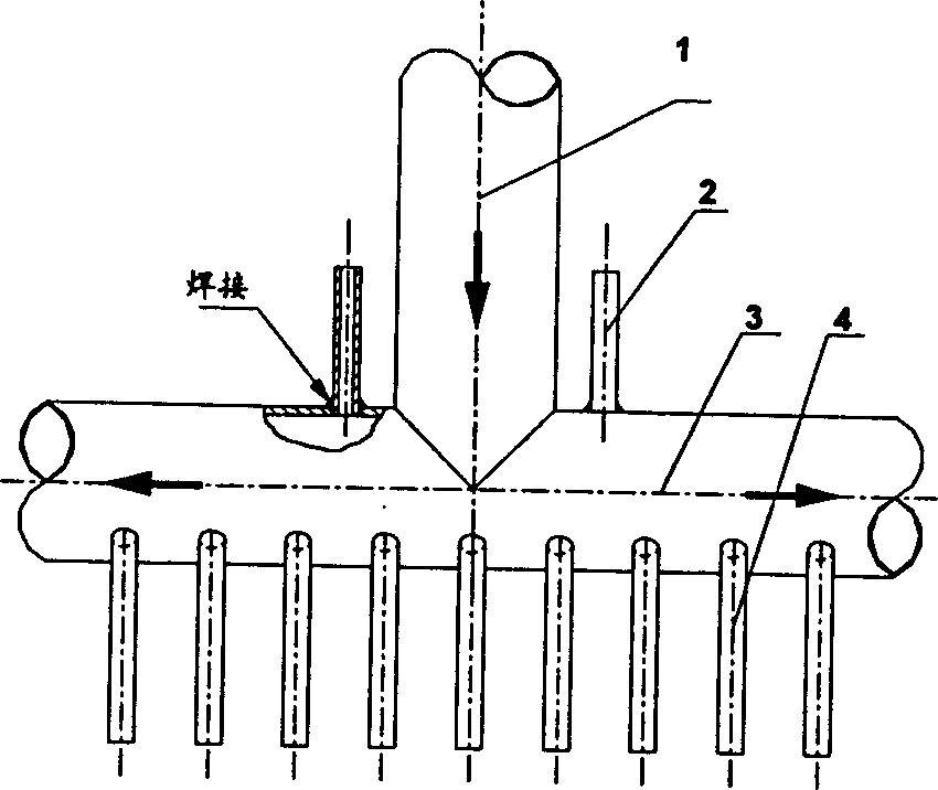
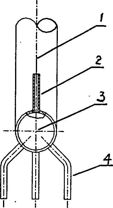
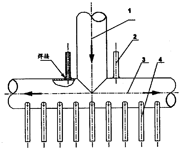
[0012] The vortex-eliminating structure of the distribution header parallel pipe group with a three-way structure of the present invention is as follows: figure 1 figure 2 As shown, in the parallel pipe group system, on the upper side of the distribution header 3 and on both sides of the three-way structure introduction conduit 1, two vortex elimination outlet branch pipes 2 are drilled and welded. The distance between the vortex-eliminating outlet branch pipe 2 and the axis of the introduction conduit 1 is 1.5 times the inner diameter of the introduction conduit 1, and the diameter of the vortex-elimination outlet branch pipe 2 is the same as that of the parallel tube group 4. The vortex elimination branch pipe 2 is directly introduced into the next stage header.

[0013] When the fluid flows, a vortex is generated near the tee in the header. Since the distribution header 3 is installed with a vortex-eliminating branch pipe 2, the fluid in the vortex area can be extracted a...


PUM


Abstract

The distribution header parallel pipe group stilling structure with three-way structure includes distribution header, parallel pipe group and leading-in conduct pipe, on two sides of leading-in conduct pipe of three-way structure the stilling leading-out branch pipes are mounted respectively, and the distance of stilling leading-out branch pipe and leading-in conduct pipe axle centre is 1.5 times inner diameter of leading-in conduct pipe, and the pipe diameter is identical to the pipe diameter of pipe of parallel pipe group, and the stilling leading-out branch pipe can be directly led into next header. Said invention combines the fluidizing of fluid, and adopts stilling structure, and can make the static pressure distribution in the distribution header with three-way structure changed into stable anjd slow so as to make flow distribution in the parallel pipe group be uniform and homogeneous.

Description

Technical field: [0001] The invention relates to a vortex-eliminating structure of a parallel pipe group with a three-way structure distribution header, which is applied to a parallel pipe group system composed of a three-way structure header, and relates to the fields of chemical industry, energy, light industry and the like. Background technique: [0002] In the existing parallel pipe group system composed of three-way headers, the working medium flows into the two sides of the distribution header from the introduction conduit, and then flows into the next-stage header through the parallel pipe group. Due to the radial introduction of fluid, the static pressure distribution near the tee in the header changes greatly, causing uneven flow distribution in the parallel pipe group, resulting in accidents or abnormalities. The main reason is that when the fluid flows through the traditional three-way structure, a large vortex area is generated, which causes uneven pressure distr...

Claims


Application Information

Patent Timeline
Patent Type & Authority Applications(China)
IPC IPC(8): F15D1/02
Inventor 陆方罗永浩
Owner SHANGHAI JIAO TONG UNIV
Learn More