Permanent magnet brushless electromotor with high torque and low pulsation
A permanent magnet brushless, high-torque technology, applied in the direction of electrical components, electromechanical devices, etc., can solve the problems that it is difficult to improve the air-gap flux density waveform, affect the smooth operation of the motor, and large torque fluctuations, etc., to improve output, Effects of reducing torque ripple and increasing magnetic flux density
- Summary
- Abstract
- Description
- Claims
- Application Information
AI Technical Summary
Problems solved by technology
Method used
Image
Examples
Embodiment 1
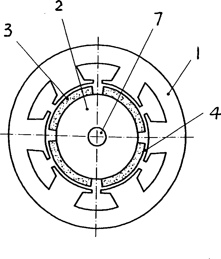
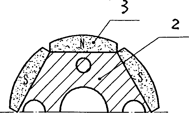
[0018] Embodiment one: if image 3 , Figure 4 As shown, a high-torque low-pulsation permanent magnet brushless motor includes a stator (1) and a rotor (2), the rotor yoke of the rotor (2) is fixed with permanent magnet poles (3), the stator (1) and the rotor (2) is provided with radial air gap (4) between; The cross-section of described rotor (2) is regular polygon, is fixed with permanent magnetic pole (3) on each side, and the width of permanent magnetic pole (3) and rotor (2) The side lengths of the sections are the same, the inner surface of the permanent magnet pole (3) is flat and combined with the rotor (2), the outer surface of the permanent magnet pole (3) is an arc surface, and the arc radius of the arc surface is larger than that of the rotor The radius of the circumscribed circle of (2) is concentric with the axis of the rotor (2).
[0019] In this embodiment, the magnetic fields of the permanent magnet poles (3) are in parallel orientation, the air gap (4) betw...
Embodiment 2
[0020] Embodiment two: if Figure 5 , Figure 6 As shown, a high-torque low-pulsation permanent magnet brushless motor includes a stator (1) and a rotor (2), the rotor yoke of the rotor (2) is fixed with permanent magnet poles (3), the stator (1) and the rotor (2) is provided with radial air gap (4) between; The cross-section of described rotor (2) is regular polygon, is fixed with permanent magnetic pole (3) on each side, and the width of permanent magnetic pole (3) and rotor (2) The side lengths of the sections are the same, the inner surface of the permanent magnet pole (3) is flat and combined with the rotor (2), the outer surface of the permanent magnet pole (3) is an arc surface, and the arc radius of the arc surface is less than Radius of the circumscribed circle of the rotor (2).
[0021] In this embodiment, the magnetic fields of the permanent magnet poles (3) are in parallel orientation, and the magnetic poles are each in a convex arc shape, and the air gap (4) bet...
Embodiment 3
[0022] Embodiment three: as Figure 7 , Figure 8 As shown, a high-torque low-pulsation permanent magnet brushless motor includes a stator (1) and a rotor (2), the rotor yoke of the rotor (2) is fixed with permanent magnet poles (3), the stator (1) and the rotor (2) is provided with a radial air gap (3); the cross section of the permanent magnet pole (3) is drum-shaped, and the cross section of the rotor (2) is a concave arc on the side length of a regular polygon , the surface combined with the permanent magnet pole (3) on the rotor (2) is a concave arc surface corresponding to the permanent magnet pole (3), and the radius of the arc surface on the outer surface of the drum pole (3) is the same as that of the rotor ( 2) The axes are concentric, and the arc surface of the inner surface is symmetrically the same as the outer surface.
[0023] In this embodiment, due to the reasonable change of the thickness of the magnetic poles in the magnetic field orientation direction, a ...
PUM
 Abstract
Description
Claims
Application Information
 - R&D
- Intellectual Property
- Life Sciences
- Materials
- Tech Scout
- Unparalleled Data Quality
- Higher Quality Content
- 60% Fewer Hallucinations
Browse by: Latest US Patents, China's latest patents, Technical Efficacy Thesaurus, Application Domain, Technology Topic, Popular Technical Reports.
© 2025 PatSnap. All rights reserved.Legal|Privacy policy|Modern Slavery Act Transparency Statement|Sitemap|About US| Contact US: help@patsnap.com


