Treatment method of user's side equipment fault based on U interface in ring network

A technology of equipment failure and processing method, applied in the field of network communication, can solve problems such as not receiving data, and achieve the effect of improving reliability

Inactive Publication Date: 2003-04-30
BEIJING JIAXUN FEIHONG ELECTRIC CO LTD
View PDF0 Cites 4 Cited by
  • Summary
  • Abstract
  • Description
  • Claims
  • Application Information

AI Technical Summary

Problems solved by technology

The disadvantage of this networking method is that if a user-side device fails at this time, the data ring will be interrupted, and subsequent users of this user-side device will not be able to receive data from the data source.

Method used


Image

  • Treatment method of user's side equipment fault based on U interface in ring network
  • Treatment method of user's side equipment fault based on U interface in ring network
  • Treatment method of user's side equipment fault based on U interface in ring network

Examples


Embodiment Construction

[0031] The concrete implementation method of method described in the present invention combines figure 1 , figure 2 , described as follows:

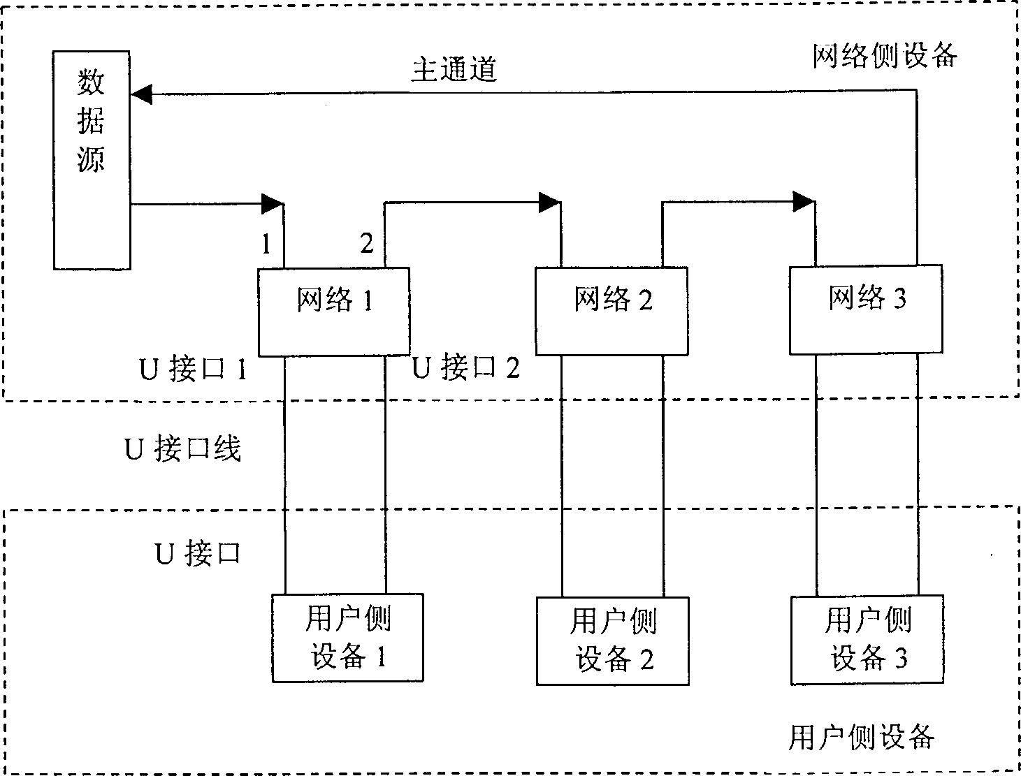
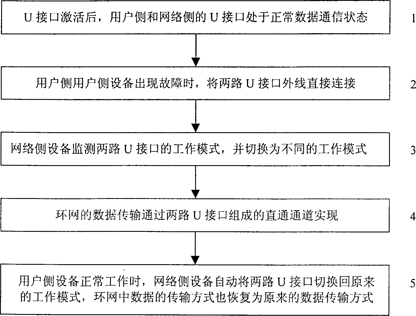
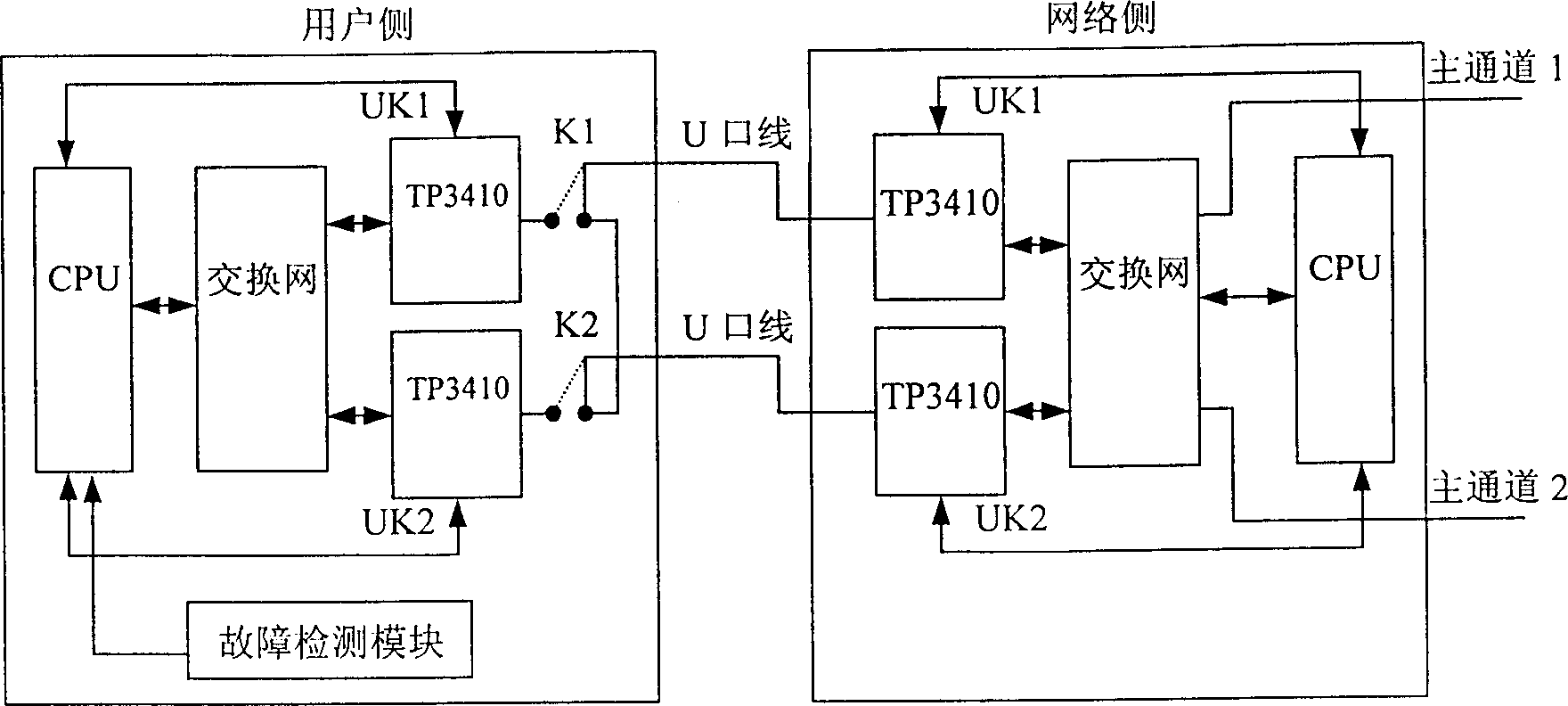
[0032] The application environment of the method of the present invention is as figure 1 As shown, the data transmission mode of the ring network is also described in the background art. The main idea of ​​the present invention is that when the user-side device detects that it is in a fault state (including power failure of the user-side device, etc.), the user directly connects U interface 1 (ie UK1) and U interface 2 (ie UK2) on the physical line , at this time, the two U interfaces on the network side are both in LT mode and are in a deactivated state and cannot perform data transmission. Therefore, it is necessary to switch the working mode of the U interface, that is, U interface 2 detect If the active state of this interface is inactive, set its own mode to NT mode, and re-initialize the U interface chip and send an activation ...


PUM


Abstract

A fault handling method for the equipment at the client side based on the U-interface in the ring network connects directly the outer line of two route U-interfaces at network side connected with theclient side equipment and one route U-interface of the two at network side is responsible to issue the activation command to activate the channel between two route U-interfaces. The data in the ring network is transmitted through the channel formed by the direct connection of two route U-interfaces for keeping the completeness of the closed ring. The device for the above-mentioned method includestwo relays connected with the outer line of two route U-interfaces at the client side, detecting module of detecting operation state and fault of the equipment at the client slide, network, exchange circuit module and CPU control circuit module at the client side.

Description

technical field [0001] The invention relates to the technical field of network communication, in particular to a method for processing failures of user-side equipment on a U-interface-based ring network. Background technique [0002] In the data communication business of ring networking, high-speed and large-capacity data transmission is adopted between network-side devices, and data communication is performed between network-side devices and user-side devices through two U interfaces, such as figure 1 shown. The U interface provides two 64kbps B channels and one 16kbps D channel data transmission channels from the network side of the communication device to the user side. The two B channels transmit voice or data information, and one D channel is mainly used to transmit control commands. Establish the circuit connection of the B channel. The U interface has two working modes: LT (Line Terminal) mode and NT (Network Terminal) mode; LT mode generally works on the network si...

Claims


Application Information

Patent Timeline
IPC IPC(8): H04L12/26H04L12/28
Inventor 李伟
Owner BEIJING JIAXUN FEIHONG ELECTRIC CO LTD
Why Eureka
Try Eureka