Small area selection
A kind of community, the selected technology, applied in the direction of selection device, radio/inductive link selection arrangement, electrical components, etc., can solve unsolvable problems, achieve the effect of small possibility, reduce risk, and shorten waiting time
- Summary
- Abstract
- Description
- Claims
- Application Information
AI Technical Summary
Problems solved by technology
Method used
Image

Examples
no. 1 example
[0107] In a first embodiment of the cell selection technique, each base station broadcasts its congestion level at regular intervals in the following one or more radio frames. The mobile unit receives these broadcast messages and whenever the signal quality difference between two cells falls below a certain threshold, the mobile unit selects the cell with the lowest degree of congestion.
[0108] This embodiment is realized based on the realization that if the load of one effective cell is much lower than that of another effective cell, in some cases, the cell with the lower load is actually preferentially used, even if the signal in this cell The quality is not as good as the signal quality in another cell.
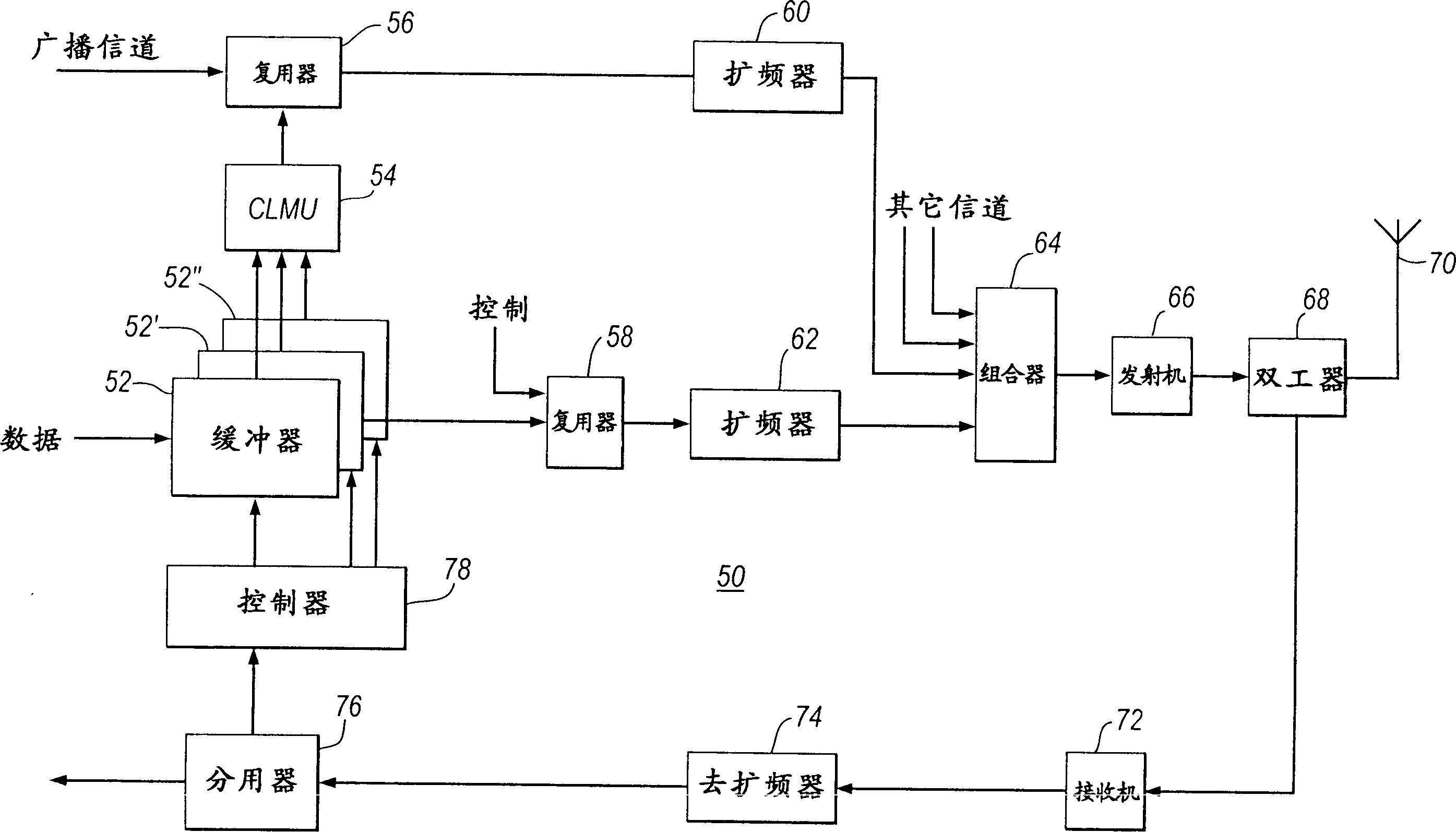
[0109] image 3 The parts of the base station that transmit signals to the mobile unit in the first embodiment are shown. Base station 50 includes: data buffers 52, 52', 52", congestion level measurement unit (CLMU) 54, multiplexer 56, multiplexer 58, spreader 60, 62, ...
no. 2 example
[0148] In a second embodiment of the cell selection technique, data is transmitted from a base station to several mobile units using a common transmission channel. A mobile unit located in the soft handoff zone monitors the shared transmit channel transmitted by the active base station to obtain a measure of the degree of congestion in the cell. Whenever the signal quality difference between two cells falls below a certain threshold, the mobile unit selects the less congested cell.
[0149] Figure 5 Sections that transmit signals to the mobile unit base station in the second embodiment are shown. The base station 120 includes: data buffers 122, 122', 122", multiplexer 128, spreader 130, transmitter 132, duplexer 134, antenna 136, receiver 138, despreader 140, demultiplexer 142 and controller 144.
[0150] In operation, data packets destined for 3 different mobile units are received from the radio network controller and buffered in the buffers 122, 122', 122". According to ...
no. 3 example
[0161] In a third embodiment of the cell selection technique, the degree of cell congestion is measured by the base station, and if the cell is too congested, the base station does not transmit data to a particular mobile unit even if the mobile unit has selected that base station for data transmission. The base station waits for its cell to be uncongested before sending the data packet, or utilizes another base station to send the data packet.
[0162] Figure 7 Parts of a base station according to the third embodiment for transmitting signals to mobile units are shown. Base station 200 includes: data buffer 202, congestion level measurement unit (CLMU) 204, multiplexers 205, 205', 205", spreader 206, combiner 208, transmitter 210, duplexer 212, antenna 214, Receiver 216 , despreader 218 , demultiplexer 220 and controller 222 .
[0163] In operation, data packets for transmission to the mobile unit are received from the radio network controller and buffered at buffer 202 . ...
PUM
 Abstract
Description
Claims
Application Information
 - R&D
- Intellectual Property
- Life Sciences
- Materials
- Tech Scout
- Unparalleled Data Quality
- Higher Quality Content
- 60% Fewer Hallucinations
Browse by: Latest US Patents, China's latest patents, Technical Efficacy Thesaurus, Application Domain, Technology Topic, Popular Technical Reports.
© 2025 PatSnap. All rights reserved.Legal|Privacy policy|Modern Slavery Act Transparency Statement|Sitemap|About US| Contact US: help@patsnap.com