Three-phase separator and device for biological sewage purification

A three-phase separator, a pair of technology, applied in biochemical instruments, biochemical equipment and methods, gas production bioreactors, etc., can solve problems such as large number of parts and large space

Inactive Publication Date: 2003-04-02
PAQUES I P
View PDF2 Cites 7 Cited by
  • Summary
  • Abstract
  • Description
  • Claims
  • Application Information

AI Technical Summary

Problems solved by technology

These different aspects result in a structure containing a large number of parts and occupying a relatively large amount of space

Method used


Image

  • Three-phase separator and device for biological sewage purification
  • Three-phase separator and device for biological sewage purification
  • Three-phase separator and device for biological sewage purification

Examples


Embodiment Construction

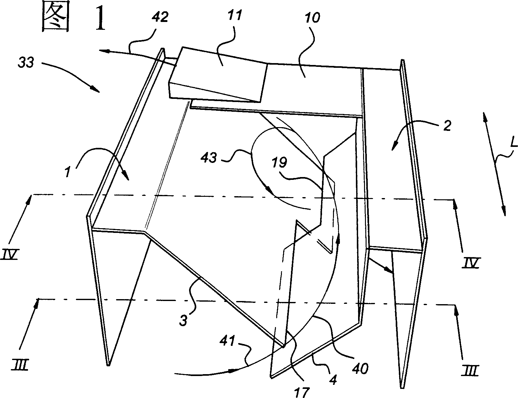
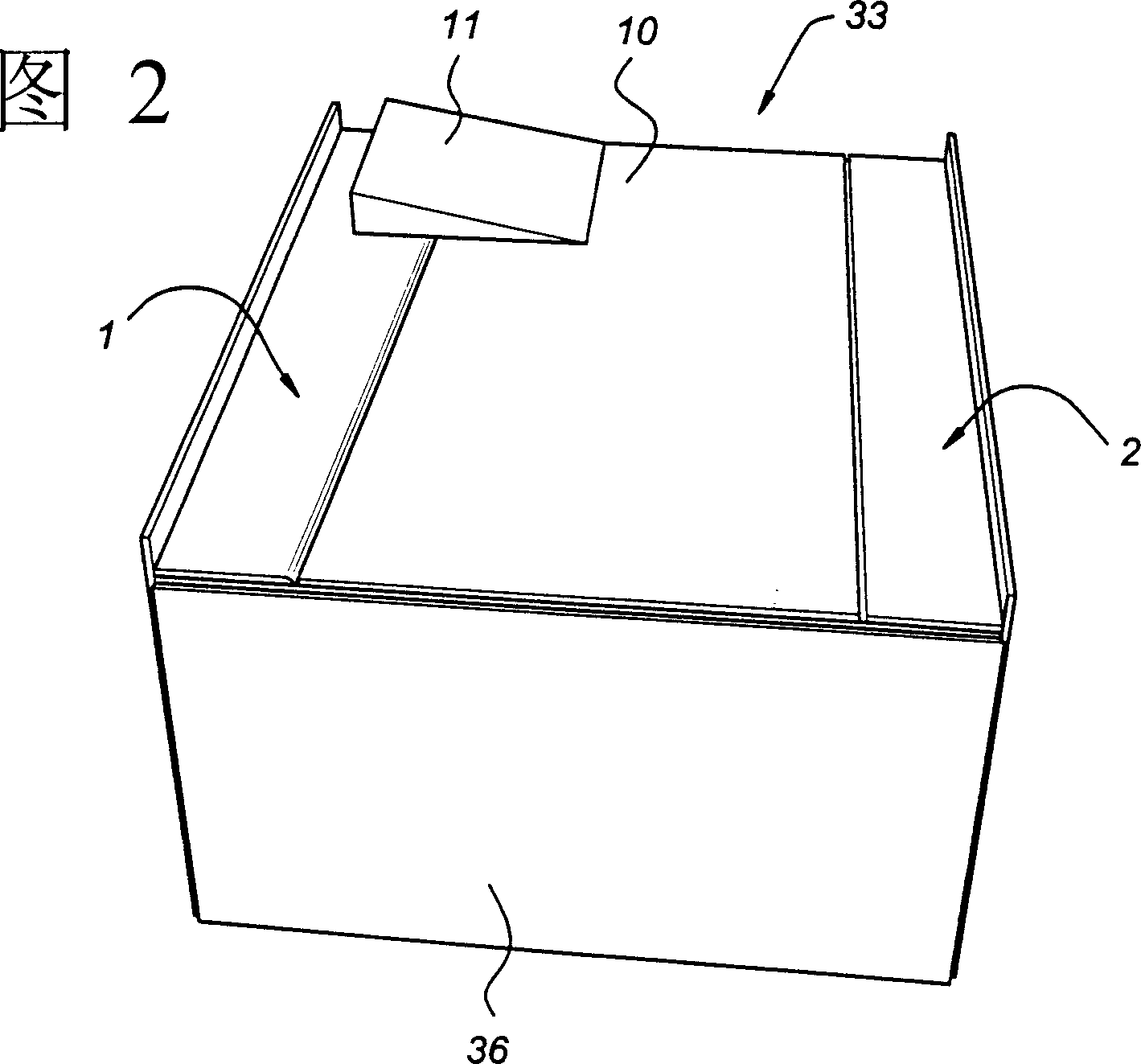
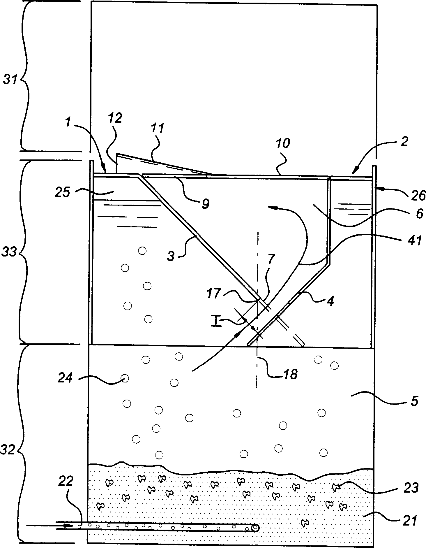
[0024] Accompanying drawing shows a three-phase separator 33, then Figure 5 A pair of three phase separators 33 are shown. The three-phase separator according to the invention comprises a pair of two gas collecting covers 1 and 2 each having a plate section 3 and 4 respectively. These plate parts 3 and 4 converge downwards and leave two elongated channels 7, 8 at their bottom ends. One of the elongated channels is the inlet channel 7 and the other channel is the outlet channel 8 . Viewed in the longitudinal direction L, the inlet channel 7 and the outlet channel 8 lie in extension of each other. Viewed perpendicularly to the longitudinal direction L, the width I of the inlet channel 7 is greater than the width E of the outlet channel 8 . The width I of the inlet channel 7 is, for example, 90 mm and the width E of the outlet channel 8 is 70 mm. More particularly, the width of the two channels ranges from 40 to 120 mm.

[0025] A reaction chamber 5 is located below the cov...


PUM


Abstract

The present invention relates to a three-phase separator (33) for separating off from a fluid gas and particles contained therein, comprising at least one pair of two gas collection caps (1, 2) extending in a horizontal longitudinal direction (L) and each having a plate section (3, 4). The plate sections converge in the downward direction. At the bottom ends the plate sections leave an inlet passage (7), elongated in the longitudinal direction, for the fluid containing particles and an outlet passage (8), elongated in the longitudinal direction, for settled particles. A discharge opening (9) for fluid, opening into the settling chamber, is provided at a level higher than the inlet and outlet passages. The inlet passage (7) and the outlet passage (8) are located in the extension of one another, viewed in the longitudinal direction. The surface area of the inlet passage is preferably greater than the surface area of the outlet passage. The discharge opening is provided level with or beyond the outlet passage.

Description

technical field [0001] The present invention relates to a three-phase separator for separating fluid gas and particles contained therein, comprising at least one pair of two gas collecting covers extending longitudinally horizontally and each having a plate portion, wherein the plate portions converge downwards, and At least one longitudinally elongated channel for fluids and particles is left at the bottom end of the plate portion, which connects a reaction chamber below the plate portion with a deposition chamber above the plate portion, wherein at least A discharge hole for fluid is provided at the level of one channel opening into the deposition chamber. Background technique [0002] Three-phase separators of this type are generally known. Mention may especially be made of EP-A244029 and EP-A949463. Three-phase separators of this type are widely used in plants for the biological purification of water. The apparatus consists of a reactor in which a bacterial floc is lo...

Claims


Application Information

Patent Timeline
Patent Type & Authority Applications(China)
IPC IPC(8): C02F3/08B01D21/00B01D21/02B01D21/24B01D21/30C02F3/02C02F3/28C02F3/30
CPCC02F3/2886C02F3/2846C12M21/04B01D21/2405C12M23/36B01D21/2494C12M27/20B01D21/2444B01D21/0042C02F3/02C12M47/02Y02W10/10
Inventor 舒尔德·许贝特斯·约瑟夫·费林加
Owner PAQUES I P
Why Eureka
Try Eureka