
Picture module

An image and sensor technology, applied in the field of small and thin image modules, can solve problems such as insufficient precision

Inactive Publication Date: 2003-03-12
SAMSUNG ELECTRO MECHANICS CO LTD
View PDF0 Cites 16 Cited by
  • Summary
  • Abstract
  • Description
  • Claims
  • Application Information

AI Technical Summary

Problems solved by technology

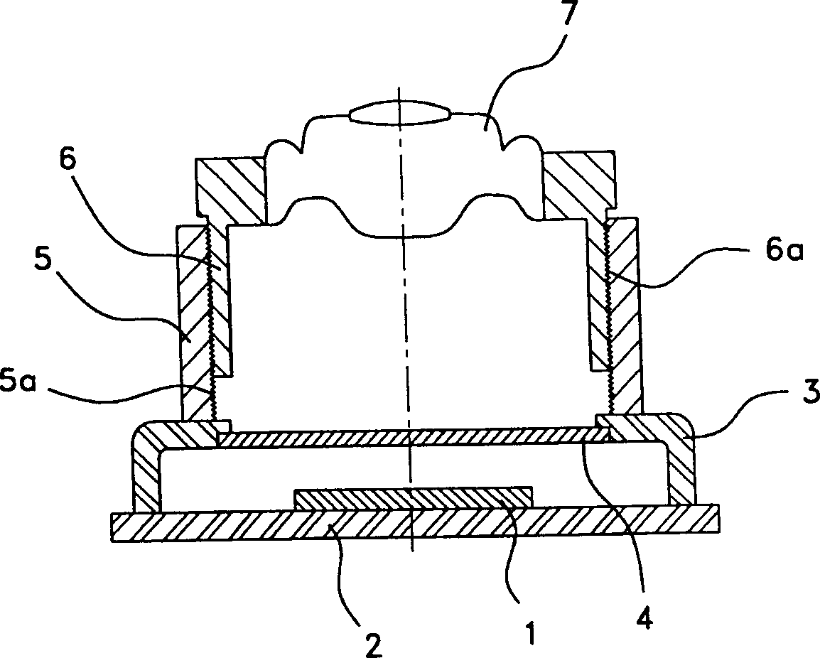
[0014] That is, the user grasps the lens shell part with one hand and rotates the thread 6a to adjust the focal point. The user directly looks at the picture, and it is inconvenient to place the lens 7 at a place far or near from the image sensor 1, and the precision is also low. not enough

Method used


Image

  • Picture module
  • Picture module
  • Picture module

Examples


Embodiment Construction

[0030] The best examples of the present invention will be described in detail below with reference to the accompanying drawings. In the following description, the same symbols are used for the same components in different drawings.

[0031] Below, the embodiment of the PC camera made according to the present invention will be described in detail with reference to the accompanying drawings.

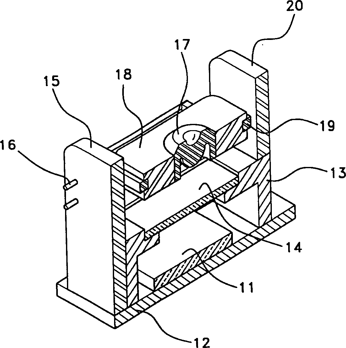
[0032] figure 2 It is a perspective view of an image module with an automatic focusing function according to the present invention; image 3 based on figure 2 A cross-sectional view of the module is shown in the image.

[0033] Such as image 3 As shown, the image module with automatic focusing function according to the present invention can be divided into an image package assembly and a lens wing unit. The above-mentioned image package assembly includes a sensor 11 , a substrate 12 , a sensor housing 13 and a sensor filter 14 . At this time, the function of the sensor 11 is to pe...


PUM


Abstract

Disclosded an image module having a function of an automatic focus adjustment based on a COB system for miniaturization and unification. The image module includes an image packaging unit, which comprises a sensor for sensing a picture image, a substrate including the sensor, a sensor cover for covering the sensor and the substrate at the outside and a sensor filter for blocking an outer environment and passing light between the sensor cover and the sensor only; and a lens blade unit, which comprises a lens blade having a lens to transmit the light at a center and a driving coil on a surface thereof, an elastic means for supplying a current to the driving coil of the lens blade and supporting the lens blade, and a magnet for forming a magnetic field to enable the lens blade to shift up and down due an electromagnetic force, and thereby lowering power consumption and production cost and improving reliability on a product thereof.

Description

technical field [0001] The invention relates to a small and thin image module with an automatic lens focusing method. Background technique [0002] A general image module is used in a digital camera or a terminal for visual communication to capture an image, connect it to a computer, and have the function of making visual communication or desired content easier to receive. And recently, the frequency of use of such image modules is gradually increasing. [0003] In particular, the recent development of communication methods using computers and the infrastructure for this purpose are increasing at an ever-increasing rate. [0004] Image sensors generally used in digital cameras or screen communication terminals can be broadly classified into charge coupled type (hereinafter referred to as CCD) and high packing density complementary metal-oxide semiconductor type (hereinafter referred to as CMOS). [0005] The CCD method is a typical example of an optical system based on an ...

Claims


Application Information

Patent Timeline
Patent Type & Authority Applications(China)
IPC IPC(8): G03B13/36G02B7/02G02B7/08G02B7/09H01L31/0203H01L31/0232H04N25/00
CPCH01L31/0203H04N5/23212H01L27/14618G02B7/08H01L31/0232H04N5/2253H01L2924/0002H01L31/02325H01L27/14623H04N23/54H04N23/55H01L2924/00H04N23/00
Inventor 崔云河金永俊
Owner SAMSUNG ELECTRO MECHANICS CO LTD
Learn More