Camera module
A camera and imaging element technology, applied in image communication, installation, television, etc., can solve problems such as thinning, miniaturization, and increasing voice coil motor 953
- Summary
- Abstract
- Description
- Claims
- Application Information
AI Technical Summary
Problems solved by technology
Method used
Image
Examples
no. 1 approach
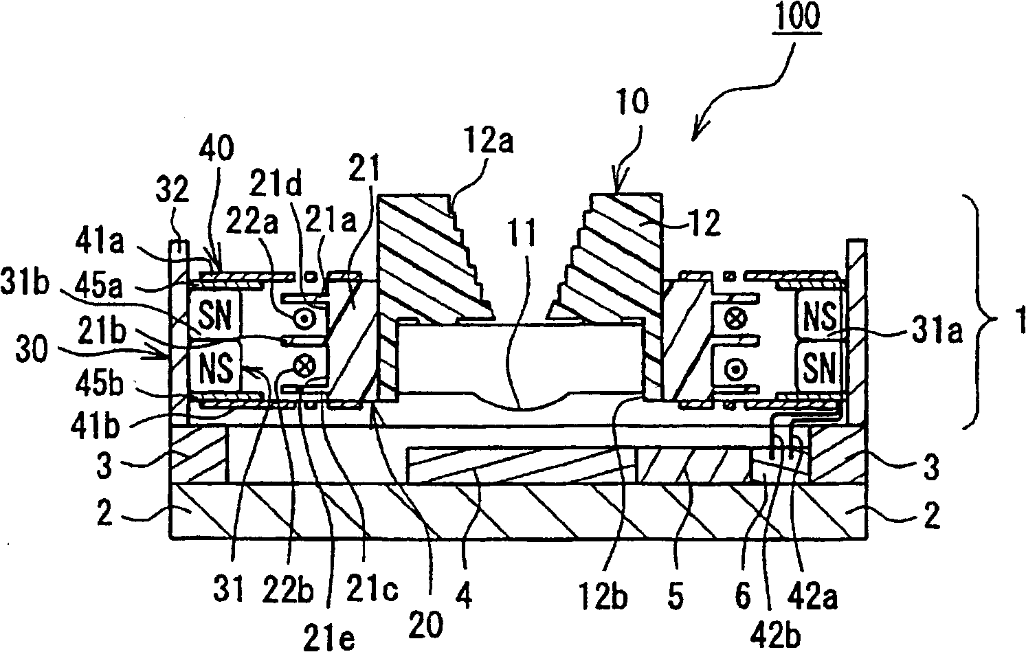
[0063] A camera module according to a first embodiment of the present invention will be described with reference to the drawings. figure 1 It is a sectional view showing the structure of the camera module according to the first embodiment of the present invention.
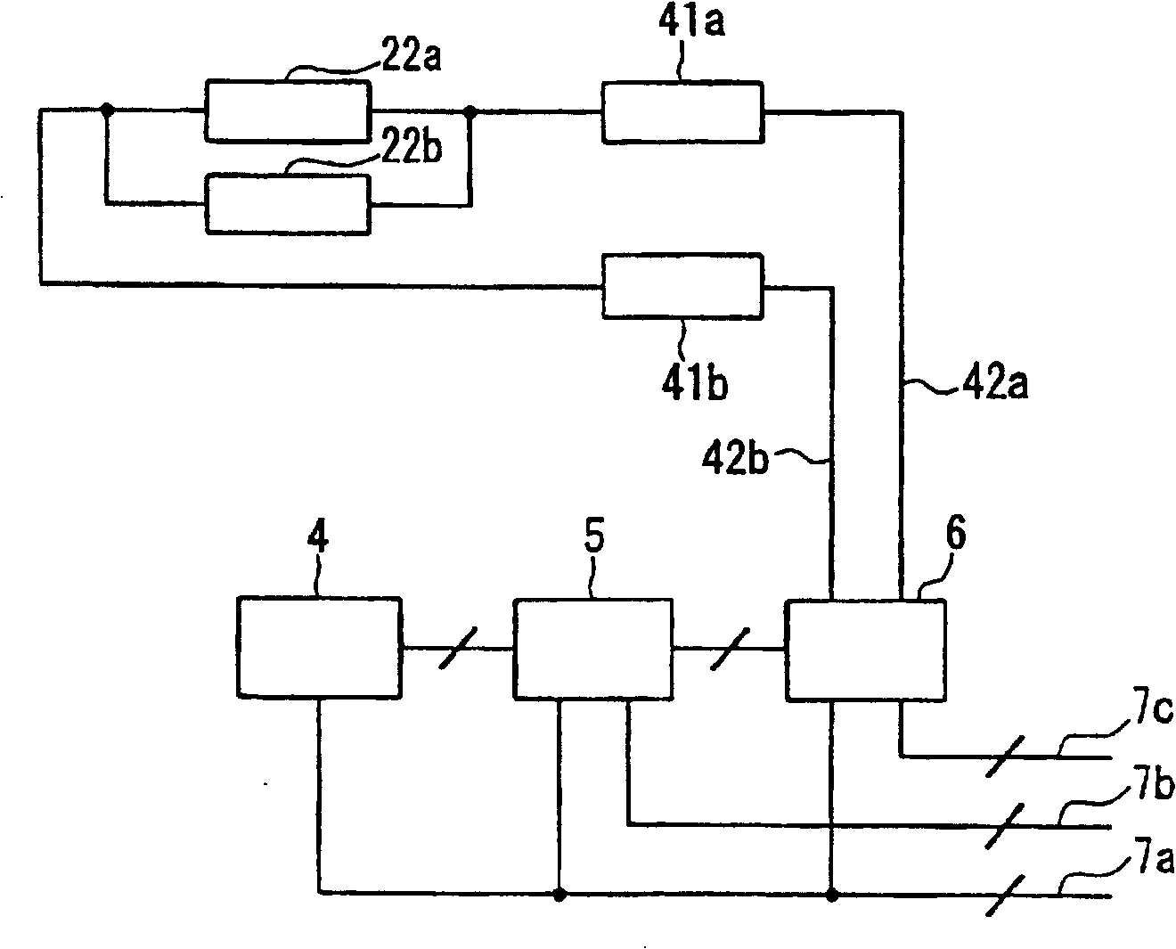
[0064] exist figure 1 Among them, the camera module 100 includes a lens module 1 , a substrate 2 , a support portion 3 , an imaging element 4 , a control element 5 , and a drive element 6 . The lens module 1 includes a lens unit 10 , a movable base 20 , a fixed base 30 , and a connection unit 40 .
[0065] The lens unit 10 has a lens 11 and a lens holder 12 . The lens 11 is formed by injection molding or cutting processing of glass or resin, and functions to bend light. Furthermore, the lens 11 is desirably made of a material with a high refractive index and low dispersion. Furthermore, the lens holder 12 is produced by injection molding or the like using resin or the like. The lens holder 12 is substantially ...
no. 2 approach
[0110]A camera module according to a second embodiment of the present invention will be described with reference to the drawings. 9A is a plan view showing the structure of the lens module according to the second embodiment of the present invention, FIG. 9B is a cross-sectional view showing the lens module according to the second embodiment of the present invention, and FIG. 9C is a sectional view showing the structure of the lens module according to the second embodiment of the present invention. Bottom view of the lens module. FIG. 9B is a sectional view taken along line 9B-9B of FIGS. 9A and 9C in the direction of the arrow.
[0111] Furthermore, the camera module of the second embodiment differs in the structure of the lens module from the camera module of the first embodiment. That is, in the camera module of the second embodiment, the figure 1 In the camera module 100 shown, the lens module 201 of the second embodiment may be used instead of the lens module 1 . For th...
no. 3 approach
[0130] A camera module according to a third embodiment of the present invention will be described with reference to the drawings. 10 is a plan view showing the structure of the upper spring (lower spring) of the camera module according to the third embodiment of the invention.
[0131]The shapes of the upper spring 341a and the lower spring 341b of the camera module according to the third embodiment are the same as those of Figure 7 The camera module according to the first embodiment shown has different upper springs 41a and lower springs 41b. Specifically, the upper spring 41a and the lower spring 41b in the first embodiment have four arms, but the upper spring 341a and the lower spring 341b according to the third embodiment have two arms. Other configurations of the camera module according to the third embodiment are the same as those of the camera module according to the first embodiment. That is, in the camera module of the third embodiment, the figure 1 In the camera ...
PUM
 Abstract
Description
Claims
Application Information
 - R&D
- Intellectual Property
- Life Sciences
- Materials
- Tech Scout
- Unparalleled Data Quality
- Higher Quality Content
- 60% Fewer Hallucinations
Browse by: Latest US Patents, China's latest patents, Technical Efficacy Thesaurus, Application Domain, Technology Topic, Popular Technical Reports.
© 2025 PatSnap. All rights reserved.Legal|Privacy policy|Modern Slavery Act Transparency Statement|Sitemap|About US| Contact US: help@patsnap.com


