Tee joint shape optimization design method

An optimized design and three-way technology, applied to mechanical equipment, branch pipelines, pipes, etc., can solve problems such as limited reinforcement effect and insufficient reinforcement

Inactive Publication Date: 2003-03-12
XIAN UNIV OF TECH
View PDF0 Cites 6 Cited by
  • Summary
  • Abstract
  • Description
  • Claims
  • Application Information

AI Technical Summary

Problems solved by technology

On the one hand, this is compatible with the early manual design tools. On the other hand, such reinforcement shapes are not completely designed according to the needs of structural strength. Some places that need more reinforcement are not fully reinforced, and some do not need reinforcement. On the contrary, the place has been strengthened too much, and the reinforcement effect is limited

Method used


Image

  • Tee joint shape optimization design method
  • Tee joint shape optimization design method
  • Tee joint shape optimization design method

Examples


specific Embodiment

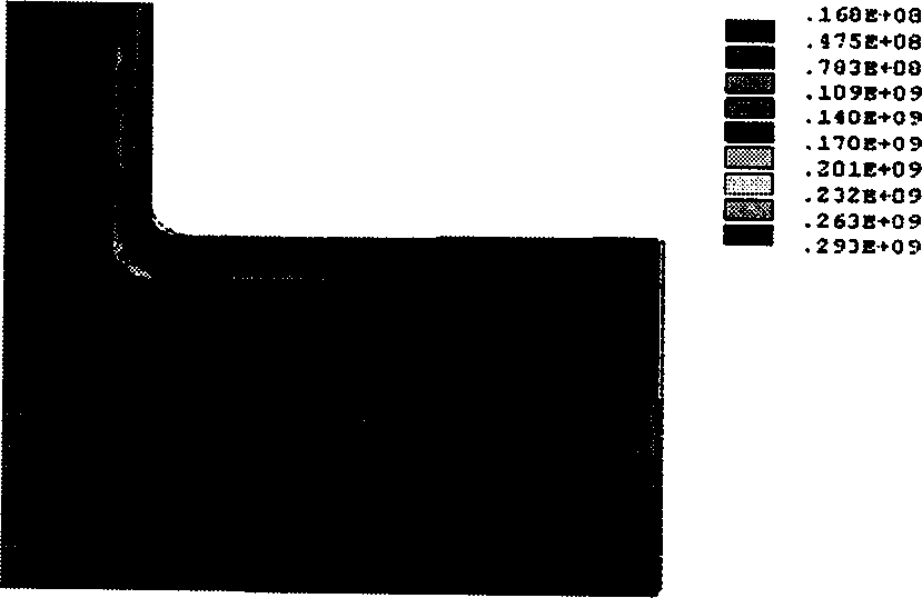
[0046] The following is the inventor's description of the technical solution adopted by the present invention by taking the optimization process of the hot extrusion tee used on the main steam pipeline of the 300MW steam turbine unit as an example. The maximum stress of the original design is 293MPa. After geometric correction, when the maximum correction amount is 10% of the outer diameter of the main pipe, the maximum stress is reduced by 52.2%, and the stress concentration factor is reduced from 3.74 to 1.79. Since the stress drop and the maximum correction amount are roughly linear in this range, the specific correction amount can be selected according to the expected maximum stress for the corresponding structure.

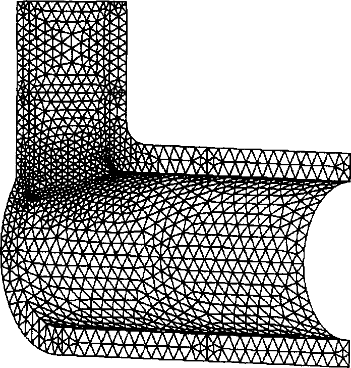
[0047] figure 1 It is a three-way structure diagram. Tee working pressure is 18.44MPa. Due to the relatively high pressure, the working deformation is relatively large, and the connecting pipe connected to it also has a large deformation near the end face. ...


PUM


Abstract

A method for optimizing the shape design of three-way includes such steps as calculating stress, and modifying boundary shape to obtain a low-stress three-way. It is characterized by the trade-off between the structure modification and stress decreasion.

Description

1. Technical field [0001] The invention belongs to the field of mechanical design, and relates to a mechanical structure shape optimization design, in particular to a tee shape optimization design method. 2. Background technology [0002] Tee is a common structure in pressure vessels and pressure piping systems, and it is widely used in thermal power plants, nuclear reactors, petrochemical and other industries. [0003] The tee designed according to the existing tee structure design code will form a relatively high stress concentration at the corner of the inner inertia line of the main pipe and the branch pipe, see "Stress Analysis and Strength Design of Pressure Vessels", pages 140-141, As a result, the tee becomes a relatively easy-to-damage component in the pipeline. [0004] Economically speaking, the cost of the tee structure itself is not very high, but the economic loss caused by the abnormal shutdown caused by replacement or repair is often huge. . Reducing the s...

Claims


Application Information

Patent Timeline
Patent Type & Authority Applications(China)
IPC IPC(8): F16L41/00
Inventor 王世军
Owner XIAN UNIV OF TECH
Why Eureka
Try Eureka