Magnetic core, magnetic field shielding part and electronic photographic equipment with them
A shielding component, electrophotography technology, applied in the direction of electric heating device, electric recording process using charge pattern, equipment for electric recording process using charge pattern, etc., to achieve the effect of eliminating heat loss and eddy current
- Summary
- Abstract
- Description
- Claims
- Application Information
AI Technical Summary
Problems solved by technology
Method used
Image
Examples
no. 1 example
[0070] First, a first embodiment of the magnetic core related to the present invention will be discussed. The magnetic core can be easily used as an inductive element at low cost and has adjustable magnetic permeability.
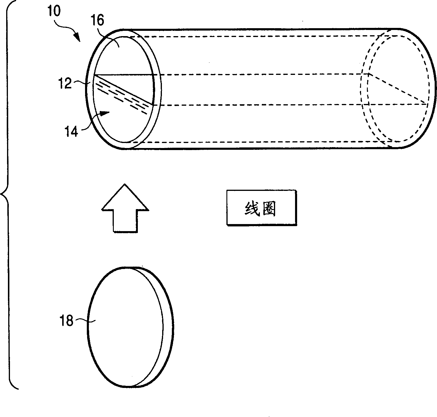
[0071] Such as figure 1As shown, the magnetic core 10 of the present invention includes a cylindrical container 12 and a collection of magnetic particles 14 . The container 12 is filled with aggregates of magnetic particles 14 maintained in a particle state. The container 12 is made of a non-magnetic material such as plastic, and a conductive material such as a coil is wound around the container 12, so that the container 12 can be used as an inductance element. The magnetic core 10 made of the assembly of the container 12 and the magnetic particles 14 is sealed with a cover 18, so that the magnetic particles 14 can be put into the container 12 and taken out from the container 12, and can be sealed so that the magnetic particles 14 will not Outflow to the ...
no. 2 example
[0119] A second embodiment of the magnetic field shielding member capable of suppressing electromagnetic field leakage easily and at low cost related to the present invention will be described below.
[0120] In the first embodiment, an example has been described in which an aggregate of magnetic particles is installed in a part of a magnetic core forming a part of an inductive element such as a coil or a transformer to improve the coil or transformer. Electromagnetic properties. However, aggregates of magnetic particles can also be used to act as a suppressor of electromagnetic field leakage. For example, aggregates of magnetic particles can be used as a magnetic field shielding member for shielding electromagnetic field leakage around magnetic field generating members such as coils or transformers with magnetic cores, air-core coils or transformers with only windings, and permanent magnets.
[0121] Magnetic field generating components such as inductive elements may be invo...
no. 3 example
[0129]A third embodiment in which an inductance element using the magnetic core of the present invention is applied to an electrophotographic apparatus as an electric device will be described below. In this third embodiment, specifically, a fixing device in which the magnetic core of the present invention is applied to an electrophotographic device will be described. The constitution of this embodiment is almost the same as that of the above-mentioned embodiment, and therefore, the same components as the above-mentioned components are denoted by the same reference numerals, and will not be described in detail below.
[0130] In general, an electrophotographic apparatus includes: an image forming unit for forming an unfixed toner image on the surface of a recording medium using electrophotography; and a fixing device unit for fixing the toner image thereon to form an unfixed toner image on the surface of the recording medium.
[0131] Heretofore, a fixing device as a fixing de...
PUM
| Property | Measurement | Unit |
|---|---|---|
| Particle size | aaaaa | aaaaa |
| Bulk density | aaaaa | aaaaa |
| Saturation magnetization | aaaaa | aaaaa |
Abstract
Description
Claims
Application Information
 - R&D
- Intellectual Property
- Life Sciences
- Materials
- Tech Scout
- Unparalleled Data Quality
- Higher Quality Content
- 60% Fewer Hallucinations
Browse by: Latest US Patents, China's latest patents, Technical Efficacy Thesaurus, Application Domain, Technology Topic, Popular Technical Reports.
© 2025 PatSnap. All rights reserved.Legal|Privacy policy|Modern Slavery Act Transparency Statement|Sitemap|About US| Contact US: help@patsnap.com


