Low power mode and feedback arrangement for switching power converter

A switching power and converter technology, which is applied in the direction of converting DC power input to DC power output, output power conversion devices, instruments, etc., can solve the problem of switching loss, reduced efficiency, ineffective use of battery power, and battery charging cycle. reduction and other issues

Inactive Publication Date: 2003-02-19
CHAMPION MICROELECTRONICS
View PDF0 Cites 9 Cited by
  • Summary
  • Abstract
  • Description
  • Claims
  • Application Information

AI Technical Summary

Problems solved by technology

However, as the power level drawn by the load decreases, switching losses become significant relative to the power level drawn from the source
At this time, when the power consumption of the load is at a low level, the switching loss will significantly reduce the efficiency
However, efficiency is an important performance indicator for switching power converters. For example, when powered by a battery, such as in a cellular phone, low efficiency results in reduced duty cycles between battery charges.
As a result, conventional switching power converters tend not to use battery power efficiently at loads consuming lower power levels

Method used


Image

  • Low power mode and feedback arrangement for switching power converter
  • Low power mode and feedback arrangement for switching power converter
  • Low power mode and feedback arrangement for switching power converter

Examples


Embodiment Construction

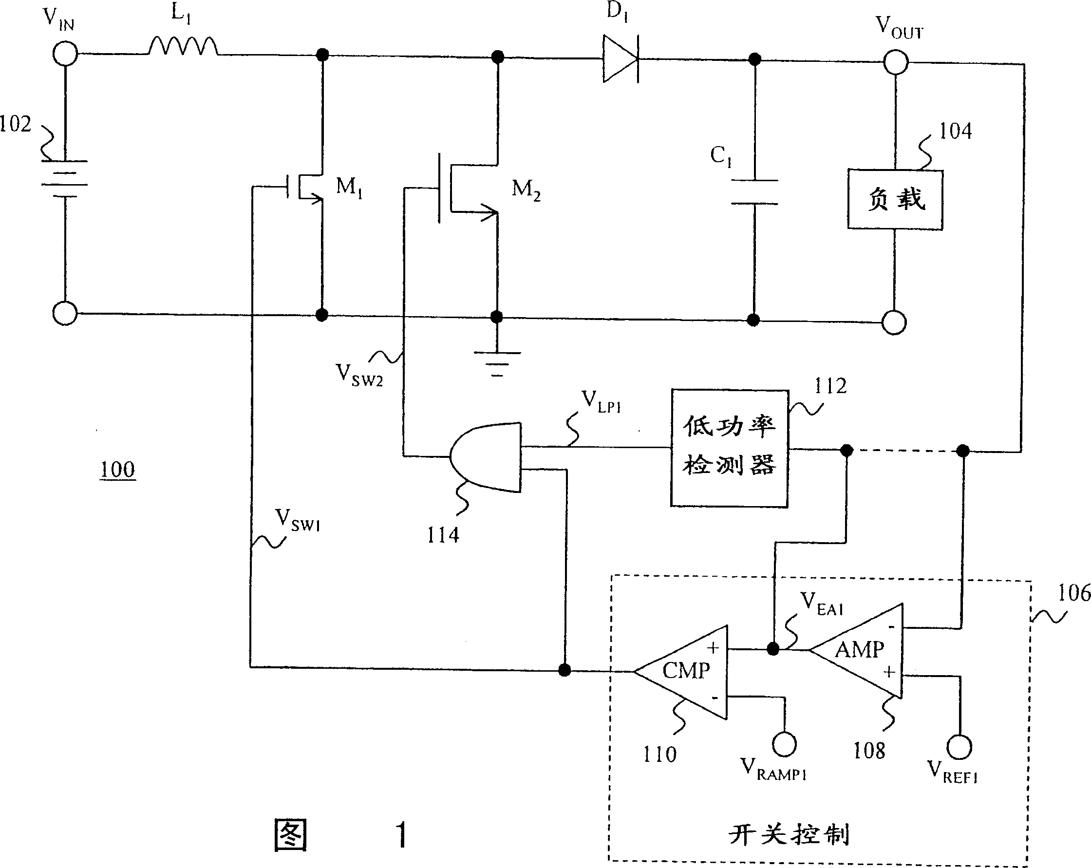
[0029] FIG. 1 is a schematic diagram illustrating a switching power converter 100 with a low power mode according to the present invention. The power converter 100 is coupled for receiving power from a power source 102 . Power source 102 may be, for example, an unregulated direct current (DC) power source such as a battery or a rectified alternating current (AC) signal. power supply 102 forms a connection with such as an inductor L 1 The first terminal of the reactive element is coupled to a voltage V in . Inductor L 1 The second terminal of can be coupled to the n-type field effect transistor M 1 the drain of the n-type field effect transistor M 2 the drain, and the diode D 1 the anode. Diode D 1 The cathode can be coupled to a capacitor such as C 1 The first end of the reactance element, and the first end of the load 104 . Transistor M 1 and M 2 source, capacitor C 1 The second end of the load 104 and the second end of the load 104 can be coupled to the ground. ...


PUM


Abstract

A low power mode and feedback arrangement for a switching power converter. Two or more main power switches, such as transistors, transfer energy from a supply to load by their opening and closing. When the load requires a relatively low power level, this condition is detected. In response, one or more of the transistor switches is disabled from switching and the reduced power requirements of the load are handled by the remaining one or more transistor switches. As a result, switching losses are reduced. This is because parasitic gate capacitance and on-resistance associated with the disabled switches no longer consume power from the power source. The invention provides significant efficiency advantages during periods when the load draws a low level of power. This is especially useful for battery-powered devices which may operate in a low power mode for extended periods of time, such as standby mode as in a portable telephone. This is because the prevention of power loss in may contribute considerably to operating time before battery re-charging is needed. However, when additional power is required, one or more previously disabled switches may be brought back into play to ensure that the power requirements of the load are met. In an audio amplifier having a H-bridge arrangement for providing a differential output signal, the invention also provides a feedback path from only one side of the load. This reduces distortion associated with open-ended operation.

Description

technical field [0001] This invention relates to the field of switching power converters and amplifiers. More particularly, the present invention relates to switching power converters and amplifiers having low power consumption modes to conserve power. Background technique [0002] In a conventional switch-mode power converter, when the main power switch is off, current from a power source, such as an unregulated power supply, flows through the inductor. This charges the inductor with energy. When the switch is opened, this energy is discharged into the capacitor. This creates a voltage across the capacitor, which can then be used to drive a load. This output voltage can be maintained at a constant and desired level by appropriately controlling the switching on and off of the switches, eg, pulse width modulation (PWM) or frequency modulation. [0003] According to PWM, the duty cycle of turning on and off the main power switch is controlled. For example, a periodic ramp...

Claims


Application Information

Patent Timeline
IPC IPC(8): H02M3/155H02M3/158
CPCY02B70/16H02M3/1584H02M3/158H02M2001/0032H02M2001/0048Y02B70/1491H02M1/088Y02B70/10H02M1/0048H02M1/0032
Inventor J·黄
Owner CHAMPION MICROELECTRONICS
Why Eureka
Try Eureka