Non reversible circuit element

A circuit component and reversible technology, applied in electrical components, circuits, waveguide-type devices, etc., can solve the problem of high resistance body temperature, and achieve the effect of increasing heat capacity, increasing degree of freedom, and improving the effect of heat dissipation

Inactive Publication Date: 2002-11-13
PANASONIC CORP
View PDF2 Cites 2 Cited by
  • Summary
  • Abstract
  • Description
  • Claims
  • Application Information

AI Technical Summary

Problems solved by technology

If such a method is adopted, when a large power input is made to the resistor body, the temperature of the resistor body will be very high

Method used


Image

  • Non reversible circuit element
  • Non reversible circuit element
  • Non reversible circuit element

Examples


Embodiment Construction

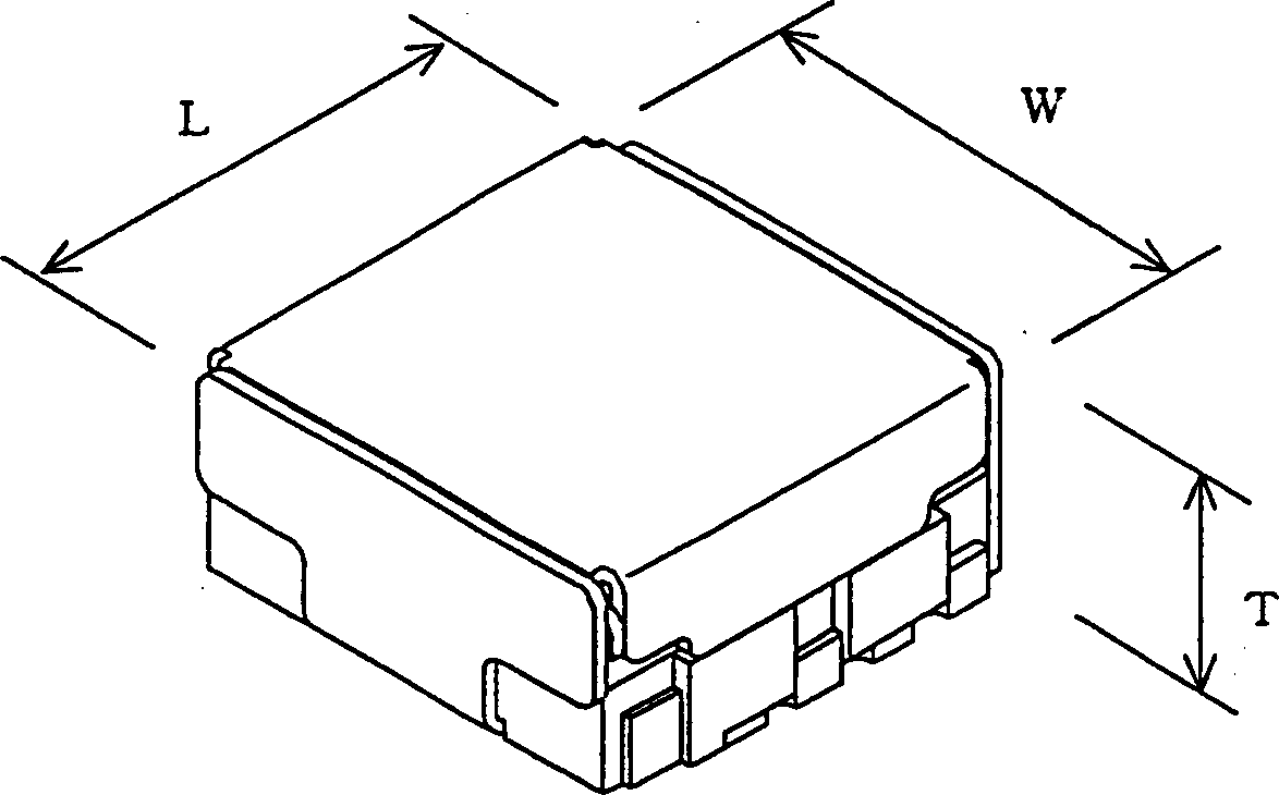
[0039] The operating power of the conventional non-reciprocal circuit element is, for example, 2.5 W in the forward direction and 0.6 W in the reverse direction, but it is ideal to have an operating power of 5 W in the forward direction. The non-reciprocal circuit element of the present invention can increase its working power without losing its low-loss characteristics in miniaturization, and can obtain a working power of about 5W in the forward direction.

[0040] The irreversible circuit element of the present invention utilizes that when an appropriate DC magnetic field is applied to a magnetic body including ferrite, it acts as an anisotropic medium on a high-frequency electromagnetic field, and makes the high-frequency input to the magnetic body The property of a signal traveling in a direction different from the direction of incidence.

[0041] Embodiments of the present invention will be described below with reference to the drawings.

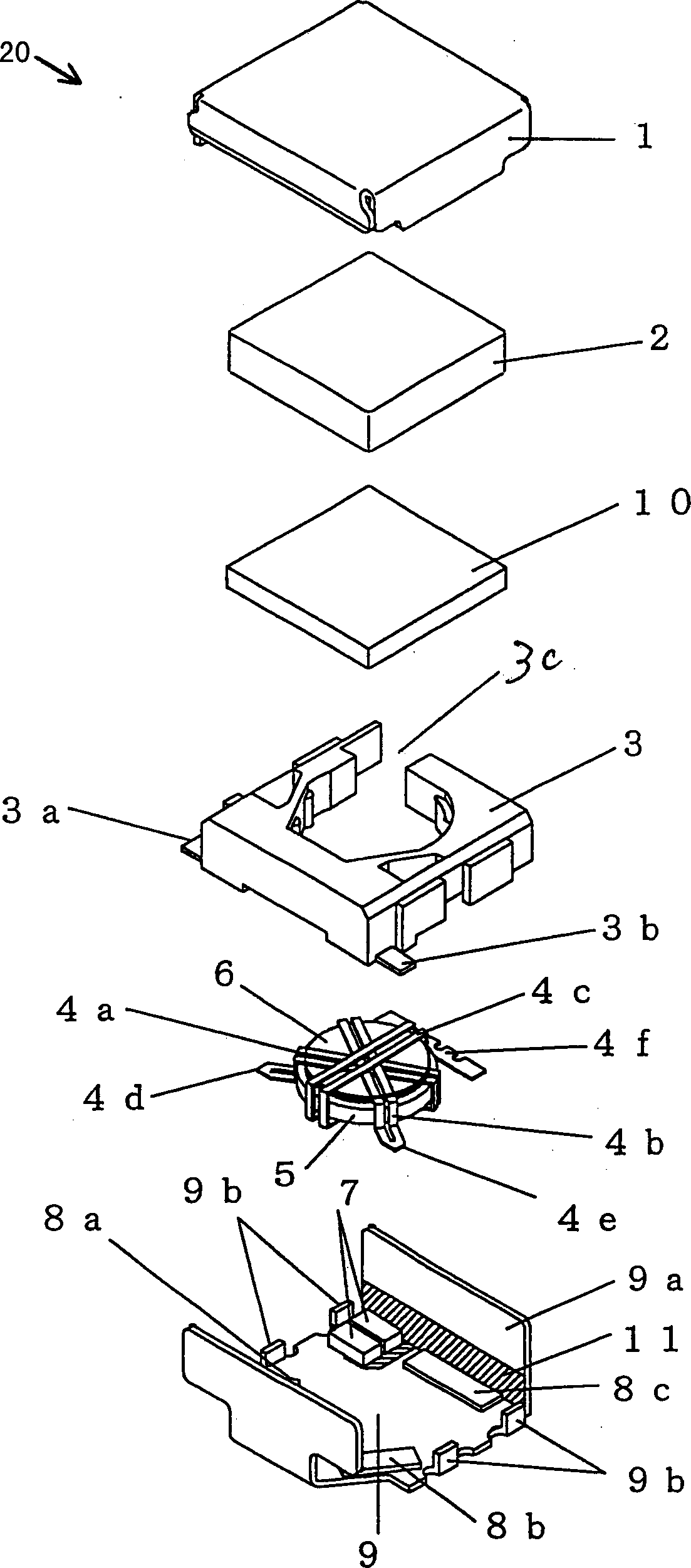
[0042] figure 1 It is an expl...


PUM


Abstract

A small non-reciprocal circuit element that can handle high-power signals without losing its characteristics. The irreversible circuit element includes a magnetic substrate capable of exhibiting anisotropy by application of a DC magnetic field. The strip lines insulated from each other are arranged at a predetermined angle on the surface of the substrate. Connect one end of these striplines to ground, and connect the other end between the capacitor and ground. The other end of a stripline is connected to a terminating resistor. The other ends of the other striplines are respectively connected to the input terminal and the output terminal. Such an irreversible circuit element has irreversible characteristics between input and output terminals. In this irreversible circuit element, an insulating heat conductor is arranged in a case. The heat conductor is used to dissipate the heat generated by the terminating resistor or the strip line.

Description

technical field [0001] The present invention mainly relates to an irreversible circuit element, in particular to an irreversible circuit element used in a mobile communication device such as a car phone and a mobile phone working in the UHF frequency band and the microwave frequency band, especially a high-power Nonreciprocal circuit components used. Background technique [0002] Due to the small size of the irreversible circuit element, it has been used in mobile communication terminal equipment from a long time ago. [0003] Such as Figure 9 As shown, in a non-reciprocal circuit element, a forward signal input from an input terminal is output to an output terminal through a low-loss path. [0004] On the other hand, if Figure 10 As shown, the signal in the reverse direction input from the output terminal is output to another terminal through a route different from the above-described route, and then absorbed by the terminating resistor connected thereto. Therefore, th...

Claims


Application Information

Patent Timeline
Patent Type & Authority Applications(China)
IPC IPC(8): H01P1/387
CPCH01P1/387
Inventor 山口修一郎德永裕美藤村宗范内仁志河野浩志
Owner PANASONIC CORP
Why Eureka
Try Eureka