Electromagnetic rope clutch

A clutch and electromagnetic technology, applied in clutches, magnetic drive clutches, non-mechanical drive clutches, etc., can solve the problems of low force chain strength, increased use, easy aging of magnetic powder, etc., to achieve large transmission torque, small size and low cost. Effect

Inactive Publication Date: 2002-10-30
CHONGQING UNIV
View PDF0 Cites 1 Cited by
  • Summary
  • Abstract
  • Description
  • Claims
  • Application Information

AI Technical Summary

Problems solved by technology

[0003] When the clutch is required to have a high operating frequency, such as dozens of times of separation and combination per second, only the magnetic powder clutch in the electromagnetic clutch can meet this requirement; when the diameter is small, such as tens of millimeters, and , it is required to transmit a large torque, such as hundreds of Nm, because the strength of the force chain connecting the magnetic powder is low, it cannot meet this requirement. In addition, the magnetic powder is easy to age, which will increase the difficulty of use.

Method used


Image

  • Electromagnetic rope clutch
  • Electromagnetic rope clutch
  • Electromagnetic rope clutch

Examples


Embodiment Construction

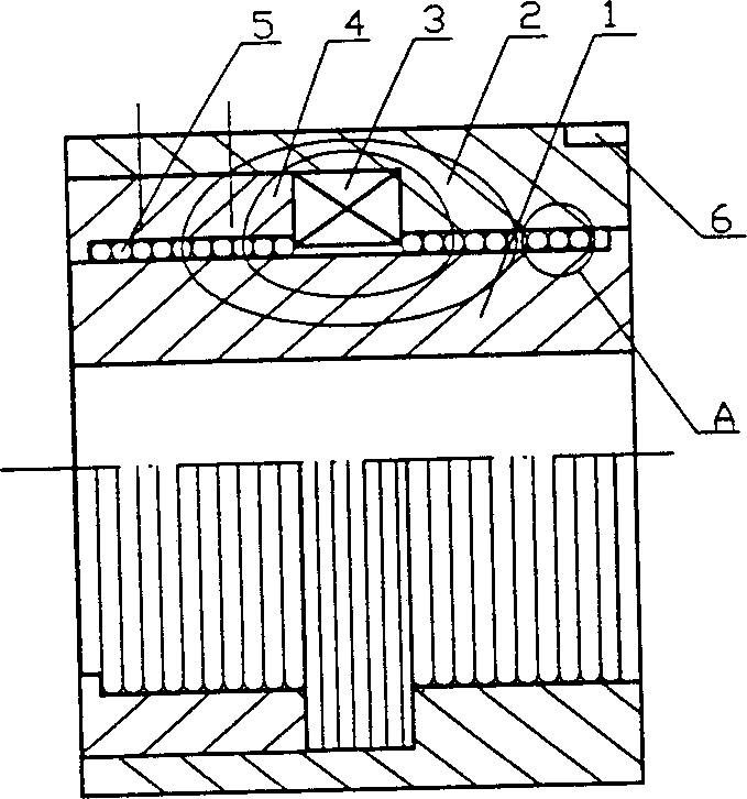
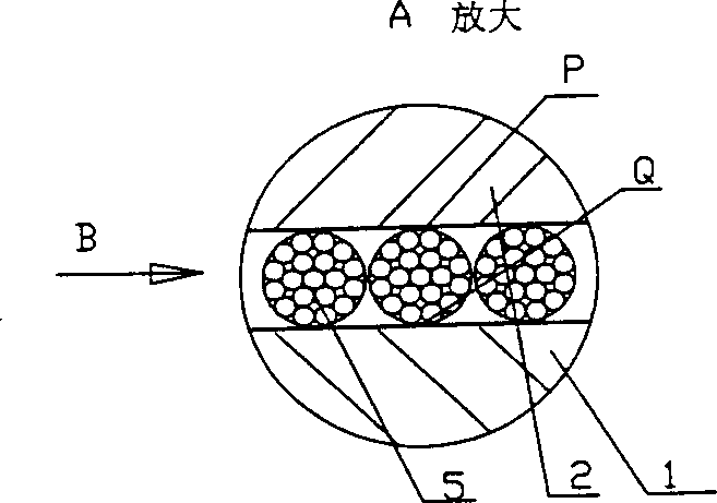
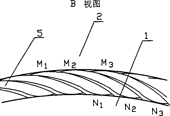
[0014] figure 1 In the given embodiment, the driving shaft and the driven sleeve are used. In this embodiment, since there is a certain gap between the steel wire rope 5 and the outer cylindrical surface of the driving shaft 1, the two do not contact; But the positive pressure is only the weight of the steel wire rope, so the friction is very small. When the driving shaft 1 rotates, the driven sleeve 2 does not rotate; when the coil is energized, an elliptical magnetic force line is formed around the coil, and the magnetic force deforms the end surface of the steel wire rope 5. , which is close to the outer edge of the driven sleeve 2 and is adsorbed on the inner wall of the sleeve, such as figure 2 As shown by the P point of , the inner edge part near the drive shaft is adsorbed on the outer cylindrical surface of the drive shaft, such as figure 2 As shown by the point Q in the figure; the magnetic line of force goes from the yoke (that is, sleeve 2) through point P of the...


PUM


Abstract

An electromagnetic cable clutch features that a steel wire cable is wound on the surface of drive axle between drive oxle and driven sleeve or the surface of driven axle between drive sleeve and driven axle and the electromagnetic coil connected to power supply is installed on the drive or driven axle or in the drive or driven sleeve. When a voltage is applied across two electrodes, the steel wire cable betwee ntwo electrodes is attracted to connect both electrodes with each other, so realizing clutch function. Its advantages are high frequency, simple structure and low cost.

Description

1. Technical field [0001] The invention relates to an electromagnetic clutch, in particular to an electromagnetic rope clutch. 2. Background technology [0002] A clutch is a device used to separate and combine two transmission parts. At present, rigid clutches, friction clutches, electromagnetic clutches, hydraulic clutches, and pneumatic clutches are widely used in machinery. [0003] When the clutch is required to have a high operating frequency, such as dozens of times of separation and combination per second, only the magnetic powder clutch in the electromagnetic clutch can meet this requirement; when the diameter is small, such as tens of millimeters, and , It is required to transmit a large torque, such as hundreds of Nm, because the force chain strength of the connection between the magnetic powder is low, it cannot meet this requirement. In addition, the magnetic powder is easy to age, which will increase the difficulty of use. 3. Contents of the invention [00...

Claims


Application Information

Patent Timeline
Patent Type & Authority Applications(China)
IPC IPC(8): F16D27/105
Inventor 梁锡昌
Owner CHONGQING UNIV
Why Eureka
Try Eureka