Transmitter, receiver, and method of data transmission
A technology of sending device and receiving device, which is applied in the direction of digital transmission system, transmission system, radio transmission system, etc., and can solve the problems such as the decrease of frequency utilization efficiency
- Summary
- Abstract
- Description
- Claims
- Application Information
AI Technical Summary
Problems solved by technology
Method used
Image

Examples
Embodiment 1
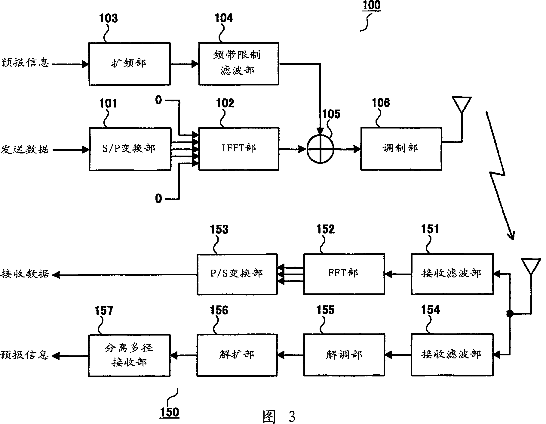
[0026] Fig. 3 is a block diagram showing the structures of a transmitting device and a receiving device according to Embodiment 1 of the present invention. The transmitting device and receiving device shown in FIG. 3 are installed in a base station device and a communication terminal device of a mobile communication system using the OFDM modulation method, respectively. In this embodiment, wireless communication between a transmitting device mounted on a base station device and a receiving device mounted on a communication terminal device will be described.
[0027] The transmitting device 100 mainly includes an S / P converting unit 101 , an IFFT unit 102 , a spreading unit 103 , a band limiting filter unit 104 , an adding unit 105 , and a modulating unit 106 .
[0028] The S / P conversion unit 101 converts serial transmission data into N (N is a natural number) subcarriers in parallel. The IFFT unit 102 performs inverse Fourier transform on N (N is a natural number) subcarrier...
Embodiment 2
[0046] Figure 5 A block diagram showing the structures of a transmitting device and a receiving device according to Embodiment 2 of the present invention. exist Figure 5 In the transmission device and reception device shown, the same components as those in FIG. 3 are given the same reference numerals as those in FIG. 3 and their explanations are omitted.
[0047] Figure 5 The transmission device 300 shown has a configuration in which a spectrum processing unit 301 is added to the transmission device 100 shown in FIG. 3 .
[0048] The spectrum processing unit 301 processes the spectrum of the band-limited signal output from the band-limiting filter unit 104 to increase the portion close to the signal transmission band (hereinafter referred to as "spectrum coloring").
[0049] The adder 105 adds the OFDM modulated signal spectrally colored by the spectrum processing unit 301 and the band-limited signal output from the band-limited filter unit 104 .
[0050] Figure 5 The...
Embodiment 3
[0055] Figure 7 A block diagram showing the structures of a transmitting device and a receiving device according to Embodiment 3 of the present invention. exist Figure 7 In the transmission device and reception device shown, the same components as those in FIG. 3 are given the same reference numerals as those in FIG. 3 and their explanations are omitted.
[0056] Figure 7 The transmission device 500 shown has a configuration in which an S / P conversion unit 501 and a plurality of frequency shift units 502 are added to the transmission device 100 shown in FIG.
[0057] The S / P conversion unit 501 performs parallel conversion on the forecast information. Spreading units 103-1 to 103-n (n is a natural number greater than or equal to 2) multiply each piece of forecast information after parallel conversion by a spreading code. Each band limiting filter unit 104-1 to 104-n limits the frequency band of the forecast information output from the corresponding spreading unit 103-1 ...
PUM
 Abstract
Description
Claims
Application Information
 - R&D
- Intellectual Property
- Life Sciences
- Materials
- Tech Scout
- Unparalleled Data Quality
- Higher Quality Content
- 60% Fewer Hallucinations
Browse by: Latest US Patents, China's latest patents, Technical Efficacy Thesaurus, Application Domain, Technology Topic, Popular Technical Reports.
© 2025 PatSnap. All rights reserved.Legal|Privacy policy|Modern Slavery Act Transparency Statement|Sitemap|About US| Contact US: help@patsnap.com