Soft magnetic powder and composite magnetic material using same
A soft magnetic powder, magnetic material technology, applied in the field of composite magnetic materials, can solve the problem of ineffective anti-noise measures
- Summary
- Abstract
- Description
- Claims
- Application Information
AI Technical Summary
Problems solved by technology
Method used
Image

Examples
Embodiment 1
[0054] Three kinds of Fe-Al-Si alloy powders with different specific surface areas were prepared using the above compositions. The specific surface areas of these samples measured by the BET method were 0.67 m 2 / g, 1.33m 2 / g and 0.17m 2 / gram.
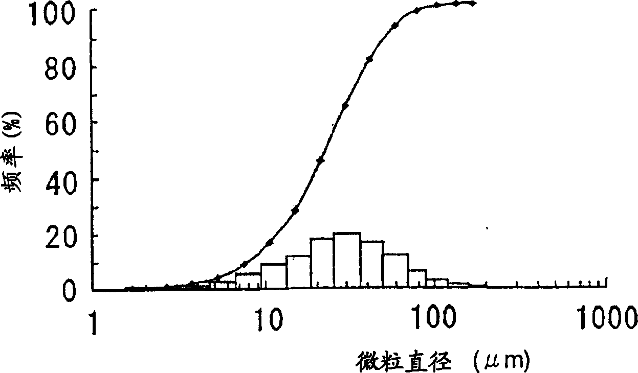
[0055] figure 1 It shows that the specific surface area is 0.67 meters 2 Particle diameter distribution of Fe-Al-Si alloy powder per gram. The particle diameter distribution curve shown in the figure has a maximum without any other peaks and valleys, which indicates that the alloy powder has a single mode particle diameter distribution. The particle diameter distribution curves of other alloy powders also show similar patterns. By analyzing the powder, it can be considered that the surface of the alloy powder particles contains excess iron compared with the bulk composition of the raw material.
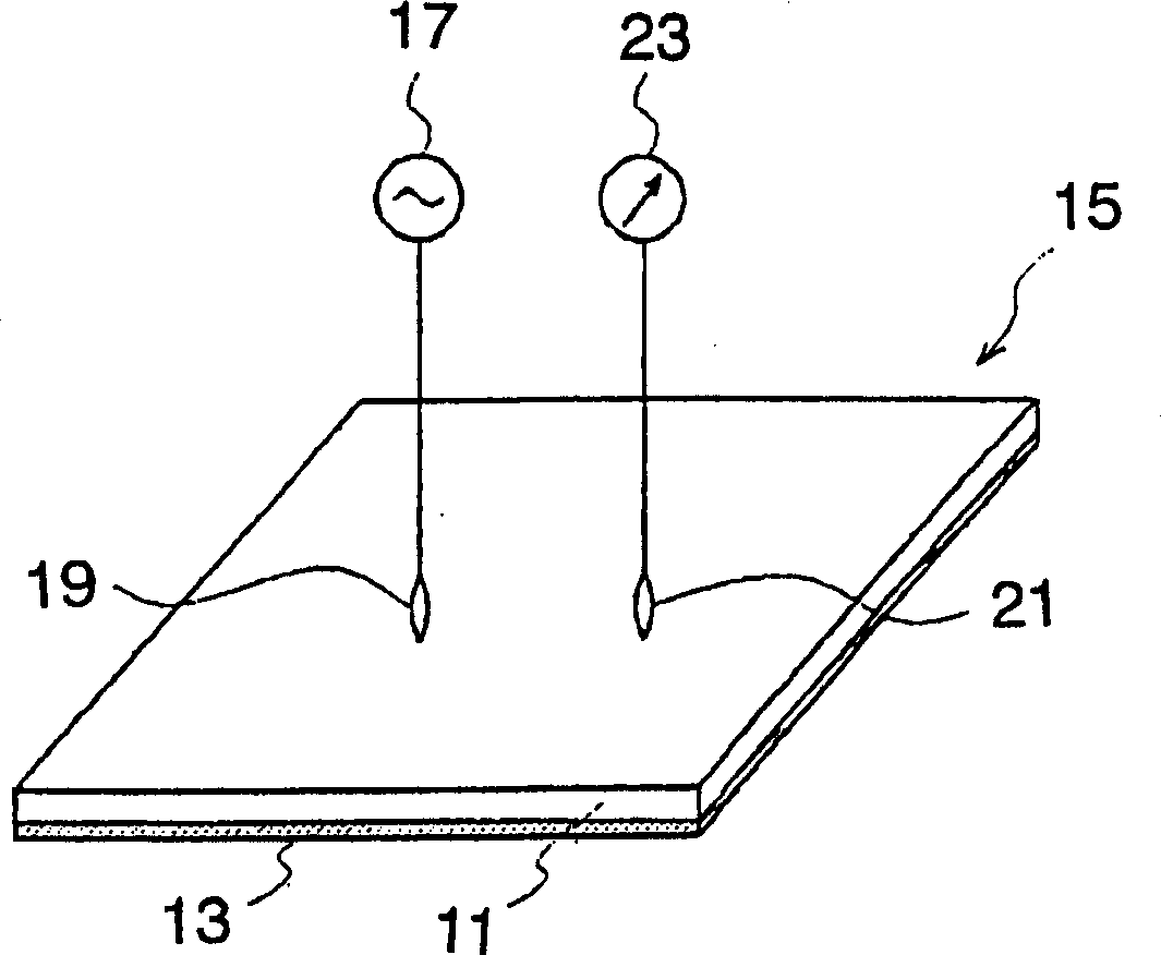
[0056] These alloy powders were formed into composite magnetic material sheets by the above-mentioned method in order to evaluate th...
Embodiment 2
[0067] An example using Fe-Ni alloy powder as the soft magnetic powder will be described below. In the present embodiment, the same method as in embodiment 1 is adopted, and the specific surface areas are respectively 0.13 m 2 / g, 0.47m 2 / g and 0.61 m 2 / g of alloy powder containing flat particles to prepare a composite magnetic material. All powders confirmed a single mode particle diameter distribution curve.
[0068] For convenience, the specific surface area will be 0.13 m 2 / g, 0.47m 2 / g and 0.61 m 2 The samples per gram of alloy powder are called No. 4, No. 5 and No. 6 samples respectively.
[0069] exist Image 6 , 7 and 8 show the evaluation results of the magnetic permeability characteristics of samples Nos. 4, 5 and 6, respectively, and these results will be discussed below. Using sample No. 4 with an alloy powder having a relatively small specific surface area, only one resonance point was observed, while samples No. 5 and 6 using alloy powders with a rel...
Embodiment 3
[0071] The flat-shaped magnetic powders described in Examples 1 and 2 were used. However, since the expression of two magnetic resonance points is believed to be due to the magnetic anisotropy of the powder particle surface, the same phenomenon can be expressed when the powder contains non-flat particles. This embodiment is described below. Magnetite (Fe 3 o 4 ) powder as magnetic powder. Also used has a specific surface area of 0.20 m 2 / g and 1.3m 2 / g of magnetic powder, and the samples containing the composite magnetic material prepared as described in Example 1, these samples are called No. 7 sample and No. 8 sample respectively.
[0072] Depend on Figure 9 and 10 The evaluation results of the magnetic permeability characteristics of samples No. 7 and No. 8 are shown, and it can be seen that the sample using magnetic powder having a relatively small specific surface area expresses two resonance points, although the powder has a single-mode particle diameter dist...
PUM
 Abstract
Description
Claims
Application Information
 - R&D
- Intellectual Property
- Life Sciences
- Materials
- Tech Scout
- Unparalleled Data Quality
- Higher Quality Content
- 60% Fewer Hallucinations
Browse by: Latest US Patents, China's latest patents, Technical Efficacy Thesaurus, Application Domain, Technology Topic, Popular Technical Reports.
© 2025 PatSnap. All rights reserved.Legal|Privacy policy|Modern Slavery Act Transparency Statement|Sitemap|About US| Contact US: help@patsnap.com