
LED module for signaling devices

A component and equipment technology, applied in the field of light-emitting diode components, can solve the problems of inflexible LED matrix and inability to use multiple lenses

Inactive Publication Date: 2002-05-22
OSRAM OPTO SEMICONDUCTORS GMBH
View PDF2 Cites 6 Cited by
  • Summary
  • Abstract
  • Description
  • Claims
  • Application Information

AI Technical Summary

Problems solved by technology

In addition, the LED matrix has the disadvantage that multiple lenses cannot be used, and the LED matrix is ​​not flexible

Method used


Image

  • LED module for signaling devices
  • LED module for signaling devices
  • LED module for signaling devices

Examples


Embodiment Construction

[0024] Description of preferred embodiments

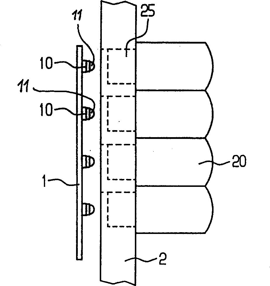
[0025] According to the first configuration of LED assembly of the present invention comprises figure 1 The thin plate 1 and the light substrate 2 in the cross-sectional view are shown. The sheet 1 is provided with a plurality of LEDs 10 arranged in a matrix of LED rows. In order to improve the heat dissipation of the LEDs, the sheet metal 1 is preferably formed from a metal plate, thereby increasing the luminous efficiency of the LEDs. Preferably, the LEDs are mounted on the thin board 1 by surface mount method (SMT). The LED10 can be manufactured according to SIEMENS SMT-TOPLED regulations approved by the German state. It is required that the circuit structure formed by the LED 10 is composed of a plurality of independent circuit branches that are not related to each other. This guarantees a high fail-safety of the assembly, for example, by connecting independent circuit branches each consisting of 15 LEDs 10 in parallel so t...


PUM


Abstract

The invention relates to an LED module having a regular array of LEDs, wherein each LED (10) is provided with a lens (20) and the LEDs (10) are mounted on a plate (1). An optics support plate (2) is provided that contains a regular arrangement of light bundling optical devices (20, 30) corresponding to the LED array. The light bundling optical devices can be lenses (20) or optical channels with reflecting side walls which are integrated into the optics support plate (2).

Description

technical field [0001] The present invention relates to light emitting diode (LED) assemblies, and more particularly to ELD assemblies mounted in signaling equipment with extremely small reflection angles. technical background [0002] In the customary railway signal setting technology, usually in the focus position of the light lens, a small-sized weak light source that is displayed forever is installed in the train conductor's line of sight height, such as the filament of an incandescent lamp. According to the highlight height of the extremely large light intensity generated by the light source under the extremely small reflection angle, the signal can be seen more clearly at a distance beyond 3km. [0003] However, existing incandescent lamps have a limited lifespan, and thus, failure of railway signaling equipment using incandescent lamps determines failure of the total installed railway signaling equipment. Therefore, in order to prevent the breakage of the incandescen...

Claims


Application Information

Patent Timeline
Patent Type & Authority Applications(China)
IPC IPC(8): B61L5/18E01F9/559E01F9/582E01F9/594F21S8/00F21V5/04F21Y115/10H01L25/075H01L33/50H01L33/58
CPCF21V5/04F21W2111/06E01F9/065E01F9/085B61L2207/02F21W2111/02F21Y2101/02B61L5/1836F21V5/007E01F9/093E01F9/559E01F9/582E01F9/594F21Y2115/10
Inventor G·怀特尔S·布吕梅尔
Owner OSRAM OPTO SEMICONDUCTORS GMBH
Learn More