Movable valves
A technology of movable valves and valve stems, which is applied in the direction of lifting valves, valve details, valve devices, etc., can solve the problems of poor sealing performance, short service life of valves, water leakage, etc., and achieve good sealing performance, long service life and wide application range Effect
- Summary
- Abstract
- Description
- Claims
- Application Information
AI Technical Summary
Problems solved by technology
Method used
Image
Examples
Embodiment 1
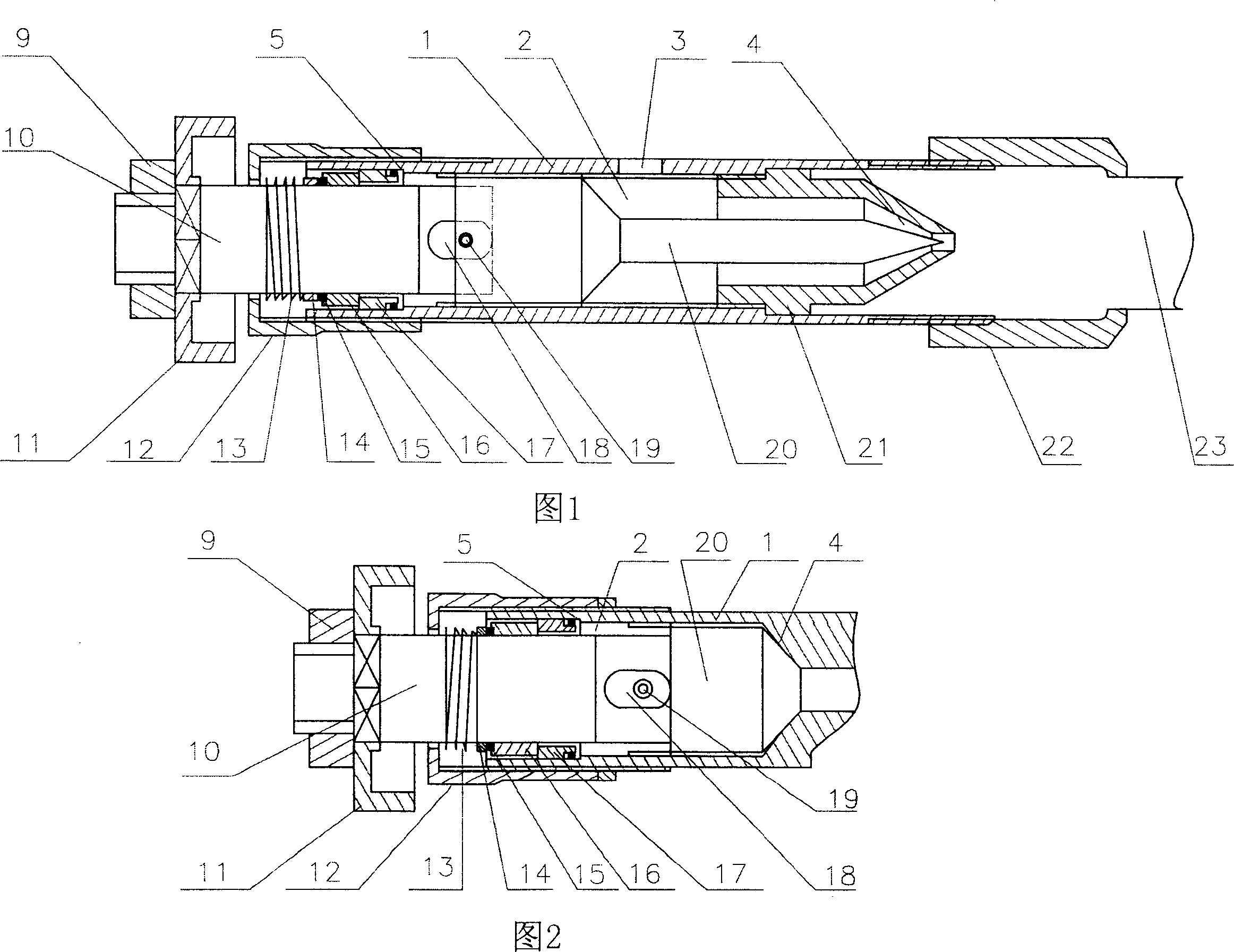
[0014] Embodiment 1: This movable valve includes a housing 1 with a lumen 2 inside and a valve stem. The valve stem is composed of a front valve stem 20 and a rear valve stem 10 connected together by a pin shaft 19. The rear valve stem 10 is A limiting hole 18 is opened, and the pin shaft 19 is located in the limiting hole 18 . Therefore, the front valve stem 20 can move back and forth within the range of the limiting hole 18 , so that the front valve stem 20 can be smoothly threaded with the inner wall of the lumen 2 . The front valve stem 20 is threadedly connected to the inner wall of the pipe cavity 2, and there is a seal between the rear valve stem 10 and the housing 1, which includes a dynamic sealing ring 16, a static sealing ring 17, and a dynamic sealing ring arranged on the rear valve stem 10. 16 and static sealing ring 17 are all made of ceramic material. The inner wall of the lumen 2 is provided with a step 5 that matches the static sealing ring 17; the rear valve...
Embodiment 2
[0016] Embodiment 2: Referring to accompanying drawing 2, the difference from Embodiment 1 is that the front end of the front valve stem 20 is tapered.
[0017] The invention has a wide application range and can be used in water, natural gas and gas pipelines, as well as various oil, chemical, hot and cold water pipelines.
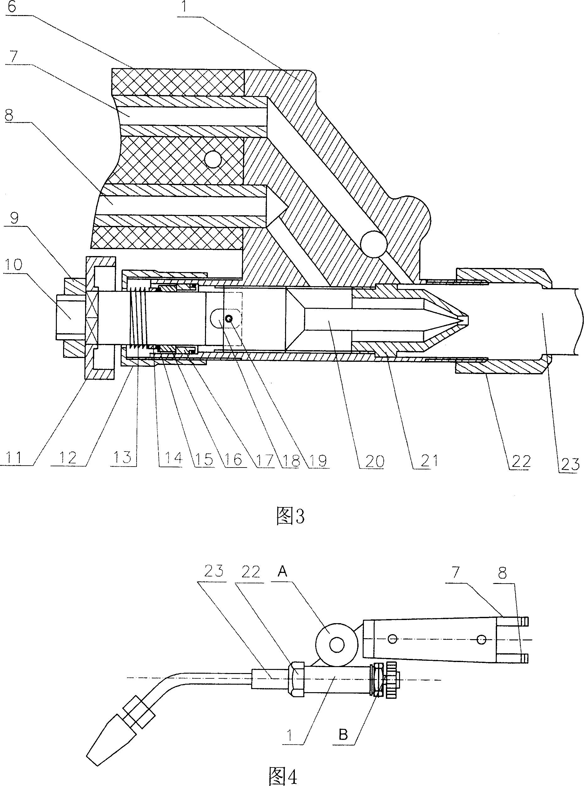
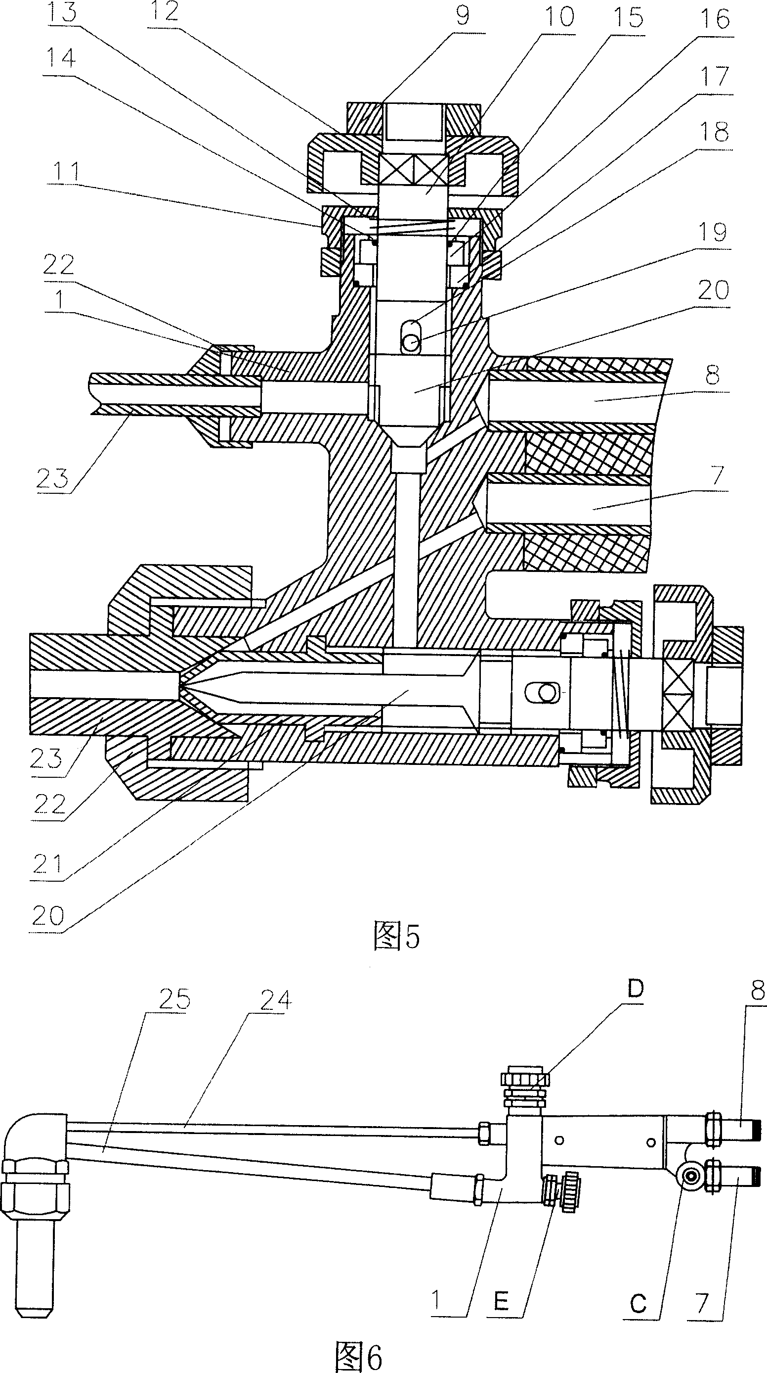
[0018] Fig. 3 is a structural schematic diagram of a movable valve used in a welding torch. The welding torch shares two movable valves A and B, the movable valve A is used to control the flow of oxygen, and the movable valve B is used to control the flow of acetylene. The oxygen tube 8 and the acetylene tube 7 are connected to the handle 6, and the handle 6 is fixedly connected to the housing 1. The housing 1 has channels communicating with the oxygen tube 8 and the acetylene tube 7 respectively, and each channel is provided with a movable valve , the active valve inlet 3 is connected to the channel. Oxygen and acetylene are mixed after being controlled...
PUM
 Abstract
Description
Claims
Application Information
 - R&D
- Intellectual Property
- Life Sciences
- Materials
- Tech Scout
- Unparalleled Data Quality
- Higher Quality Content
- 60% Fewer Hallucinations
Browse by: Latest US Patents, China's latest patents, Technical Efficacy Thesaurus, Application Domain, Technology Topic, Popular Technical Reports.
© 2025 PatSnap. All rights reserved.Legal|Privacy policy|Modern Slavery Act Transparency Statement|Sitemap|About US| Contact US: help@patsnap.com


