Rice-planting machine

A technology of rice transplanter and fuselage, which is applied to parts of planters, control devices, agricultural vehicles, etc., and can solve problems such as stopping the fuselage, being unreliable, and unable to stop the rotation of front and rear wheels.

Inactive Publication Date: 2002-01-09
YANMAR CO LTD
View PDF0 Cites 2 Cited by
  • Summary
  • Abstract
  • Description
  • Claims
  • Application Information

AI Technical Summary

Problems solved by technology

[0007] (1) Since the auxiliary brake mechanism is arranged on the upstream side of the gearbox between the engine and the gearbox, that is, on the power transmission line, when the gearbox is in a neutral state, even if the auxiliary brake mechanism works, it cannot stop the front and rear wheels. Turning, in the case of slopes such as ramps, the fuselage cannot be reliably stopped
[0008] (2) The auxiliary brake mechanism is provided on the pulley portion of the transmission input shaft, it is not exposed outside and there is no extra space when performing maintenance, therefore, the auxiliary brake mechanism cannot be easily repaired, inspected, etc. from the outside of the fuselage, poor maintenance performance
[0009] (3) When the auxiliary brake mechanism is exposed outside the fuselage in order to improve the maintenance performance, the mud sticks to the auxiliary brake mechanism, which may reduce the braking force of the auxiliary brake mechanism
[0010] (4) When the auxiliary gate mechanism and the mud removal mechanism are installed on the frame separately, the respective positions must be adjusted, and the assembly work may become complicated

Method used


Image

  • Rice-planting machine
  • Rice-planting machine
  • Rice-planting machine

Examples


Embodiment Construction

[0036] Invented embodiment

[0037] Hereinafter, embodiments of the present invention will be described with reference to the drawings.

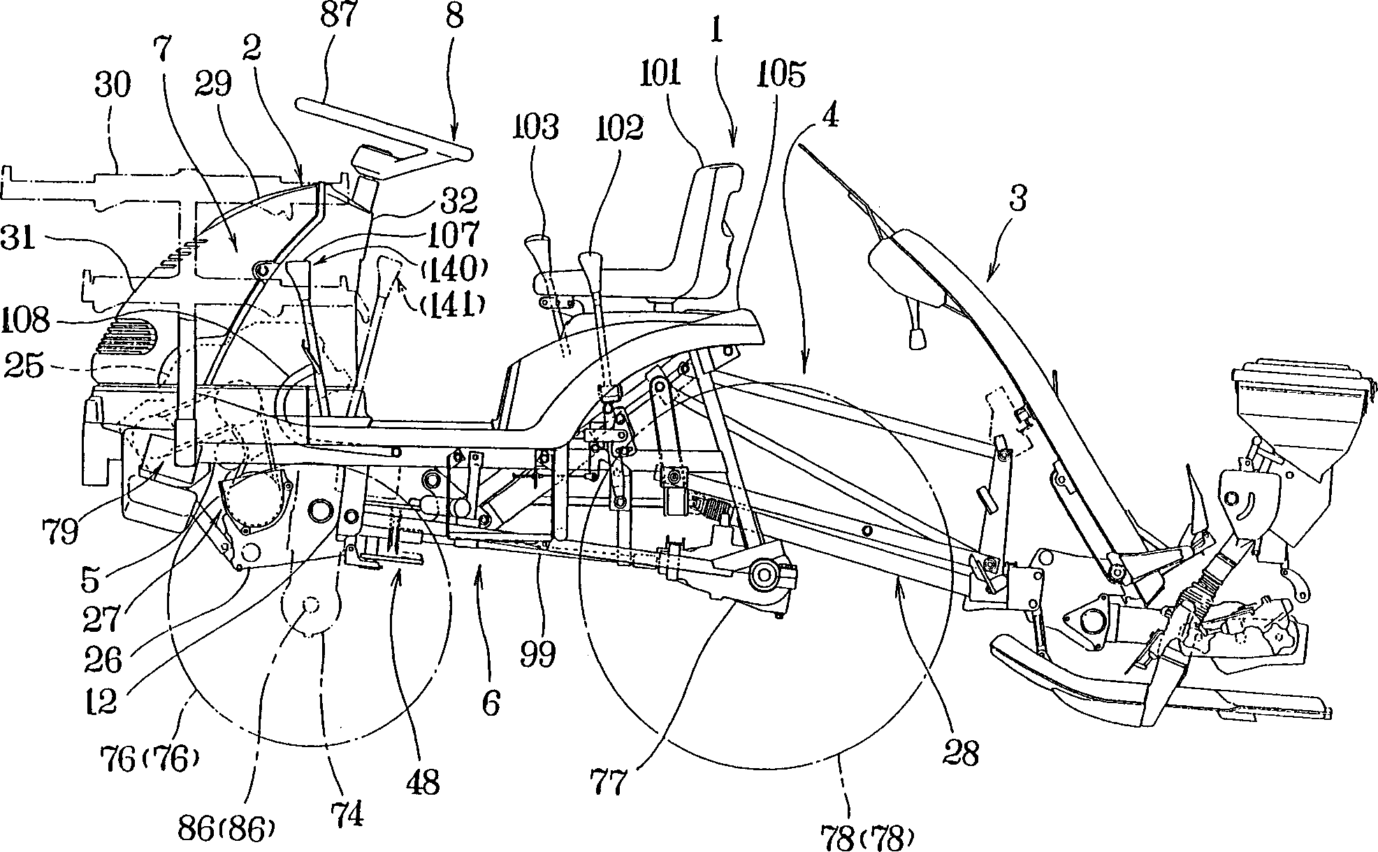
[0038] The riding rice transplanter 1 of the present invention is figure 1 As shown, the transplanting machine 3 is connected to the rear part of the walking body 2 capable of walking automatically through the lifting mechanism 4 so as to be liftable.

[0039] Walking body 2 such as figure 1 As shown, the walking part 6 is arranged on the lower part of the frame 5, on the other hand, the prime mover part 7 is arranged on the upper front side of the frame 5, and the operation control part 8 is arranged directly behind the prime mover part 7.

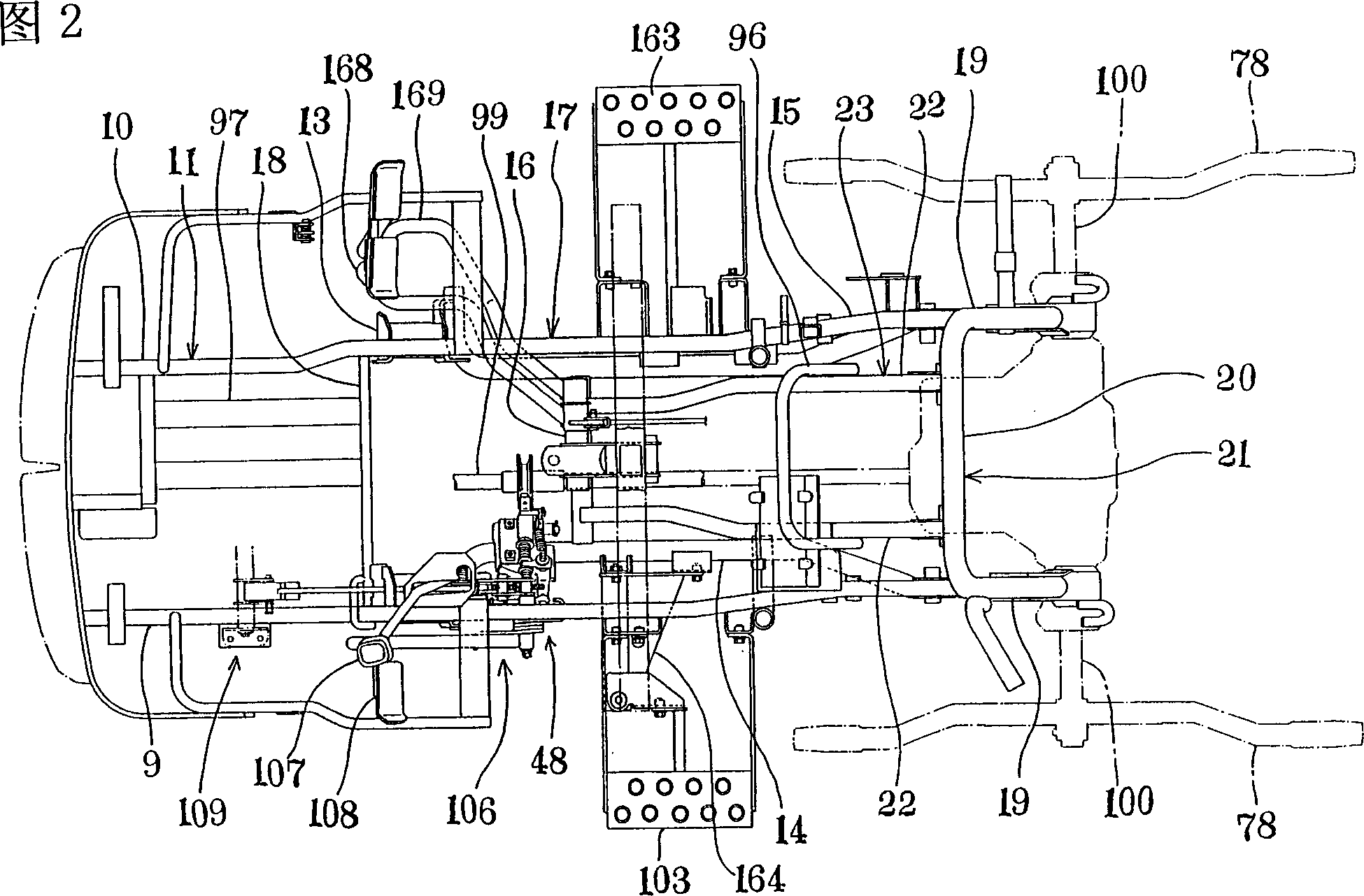
[0040] Frame 5 as figure 1 As shown in 2, a pair of left and right main pipes 9 and 10 with rectangular cross-section extending back and forth and a front pipe (not shown) erected between the front ends of the main pipes 9, 10 and having a rectangular cross-section constitute a plan view On the U-shaped ...


PUM


Abstract

A rice-planting machine including an auxiliary brake mechanism for stopping the machine body, which auxiliary brake mechanism is operatively associated with a clutch mechanism installed in a power transmission path extending from a prime mover to a running section, wherein a transmission case is operatively connected to the engine through the clutch mechanism, an axle case is operatively connected to the transmission case, and a pair of wheels are operatively connected to the axle case, thereby forming a power transmission path to transmit the engine power from the engine to the wheels, the auxiliary brake mechanism being located in the power transmission path downstream of the transmission case. Thus, even if the transmission case is held neutral, the rotation of the front and rear wheels can be stopped by the auxiliary brake mechanism, enabling the machine body to be reliably kept stopped even on an inclined surface such as a slope.

Description

Technical field [0001] The invention relates to a rice transplanter, in particular to an auxiliary brake mechanism for stopping the machine body. Background technique [0002] The traditional rice transplanter can be raised and lowered to install the transplanter at the rear of the automatic walking body. The walking body is like this, that is, it is equipped with a walking structure composed of front and rear wheels and a linkage mechanism in the lower part of the frame. On the other hand, it is equipped with a prime mover composed of an engine and a gearbox at the front of the frame, and a clutch is set on the power transmission route from the prime mover to the walking part, which is linked by a clutch-brake The mechanism links the clutch mechanism with the auxiliary brake mechanism. [0003] In the clutch-brake linkage mechanism, there is a linkage lever that can be changed between such postures, that is, when the clutch is in the connected state and the auxiliary brake mecha...

Claims


Application Information

Patent Timeline
Patent Type & Authority Applications(China)
IPC IPC(8): A01C7/20
CPCA01C7/20B60K23/02B60Y2200/22
Inventor 竹内修山本二教
Owner YANMAR CO LTD
Why Eureka
Try Eureka