Rake receiving method and device

A Rake receiving and receiver technology, applied in the field of Rake receiving methods and devices, capable of solving the problems of increasing the total buffer capacity and the like

Inactive Publication Date: 2007-07-25
NEC CORP
View PDF4 Cites 0 Cited by
  • Summary
  • Abstract
  • Description
  • Claims
  • Application Information

AI Technical Summary

Problems solved by technology

However, as described above, in the conventional rake receiving apparatus described above, since the total number of data that must be held to adjust the data timing is given by D=F×W / S, the buffer increases as the number F of fingers The total capacity of the device also increases, which is not expected

Method used


Image

  • Rake receiving method and device
  • Rake receiving method and device
  • Rake receiving method and device

Examples


Embodiment Construction

[0022] Embodiments of the present invention will be described in detail below with reference to the accompanying drawings.

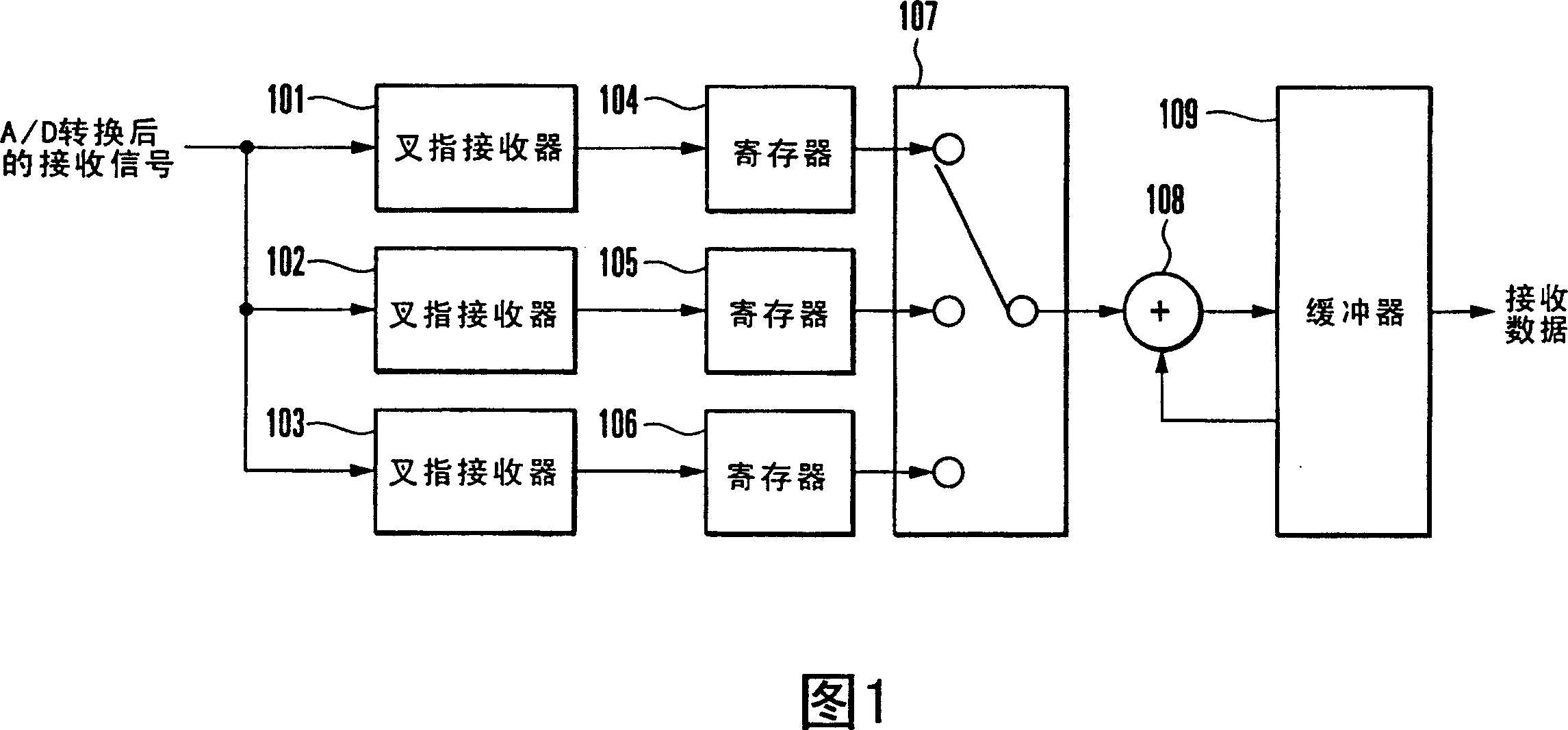
[0023] Fig. 1 shows the arrangement of a rake receiving device according to one embodiment of the present invention. The rake receiving apparatus of this embodiment includes interdigital receivers 101 , 102 and 103 , registers 104 , 105 and 106 , switch 107 , adder 108 and buffer 109 .

[0024] Interdigital receivers 101, 102, and 103 despread the A / D-converted reception signal based on paths, and output the despread data.

[0025] The register 104 temporarily holds the despread data output from the finger receiver 101 on a path basis. Similarly, registers 105 and 106 temporarily hold despread data output from interdigital receivers 102 and 103 on a path basis, respectively.

[0026] The switch 107 receives the data output from the registers 104, 105, and sequentially selects and outputs these data one by one.

[0027] The adder receives the data outp...


PUM


Abstract

A rake reception apparatus which receives and rake-combines spread signals on a path basis includes finger receivers (101-103), a switch (107), an adder (108); and a buffer (109). The finger receivers de-spread reception signals on a path basis. The switch sequentially selects de-spread data one by one on a path basis which are output from the plurality of finger receivers. The adder adds the data selected by the switch to a rake combining interim result corresponding to the data and outputs the result as a rake combining interim result after updating. The buffer holds the rake combining interim result output from the adder and outputs a rake combining interim result corresponding to data selected by the switch to the adder. A rake reception method is also disclosed.

Description

technical field [0001] The present invention relates to a rake (rake) receiving method and device, more specifically, to a rake receiving method and device for path-based receiving and despreading spread spectrum signals and rake synthesis result data. Background technique [0002] Recently, much attention has been paid to CDMA (Code Division Multiple Access) using spread spectrum technology as a high-speed, large-capacity radio communication scheme. In this radio communication scheme, communication is performed using a transmitting device and a receiving device such as those shown in FIG. 3 . [0003] The transmitting device includes a spreading unit 301 , a D / A converter 302 and a transmitting analog processing unit 303 . The receiving device includes a receiving analog processing unit 304 , an A / D converter 305 , despreading units 306 , 307 and 308 , and a rake combining unit 309 . [0004] At the transmitting end, firstly, the spreading unit 301 multiplies the transmit...

Claims


Application Information

Patent Timeline
IPC IPC(8): H04B1/40H04J13/02H04B1/707H04B1/7117
CPCH04B2201/70707H04B1/7117H04B1/712
Inventor 石井大二
Owner NEC CORP
Why Eureka
Try Eureka