Anti-explosion impact wave filtering valves

A shock filter and anti-explosion technology, which is applied in the field of anti-explosion valves, can solve the problems that the valve plate cannot quickly open the pipeline, affect the life safety of indoor personnel, and the transient performance of the valve plate is not high, so as to improve the sensitivity of feeling and eliminate Short circuit, responsive effect

Active Publication Date: 2007-05-09
常州市汇丰船舶附件厂
View PDF3 Cites 0 Cited by
  • Summary
  • Abstract
  • Description
  • Claims
  • Application Information

AI Technical Summary

Problems solved by technology

But in fact, when the shock wave enters the pipe, the high-speed and high-pressure airflow acts on the valve plate, and the valve plate overcomes the elastic force of the main spring and directly presses on the valve seat, and at the same time cuts off the fluid medium in the pipe. There is a vacuum phenomenon in the pipeline behind, so even after the shock wave disappears, the valve plate is sucked by the vacuum generated by the pipeline behind, so that the back pressure of the valve plate is still lower than the pressure at the front end of the valve plate, so when the shock wave disappears, the valve plate It is also impossible to quickly open the pipeline to restore normal circulation.
Especially for the anti-explosion valve installed at the front of the room, since the air supplied to the room is cut off, it will seriously affect the life safety of the indoor personnel, and sometimes, the equipment behind the valve will be damaged
In addition, because the front part of the valve plate of the anti-explosion valve is a flat structure, when the shock wave presses the valve plate to the valve seat, the shock wave will pass through the flow channel between the valve plate and the valve seat instantly due to the thin thickness of the valve plate. A short short circuit is formed between the front and rear of the valve plate. Since the back pressure of the valve plate is increased, this part of the back pressure must be overcome during the downward movement of the valve plate, so the transient performance of the valve plate is not high.

Method used


Image

  • Anti-explosion impact wave filtering valves
  • Anti-explosion impact wave filtering valves
  • Anti-explosion impact wave filtering valves

Examples


Embodiment Construction

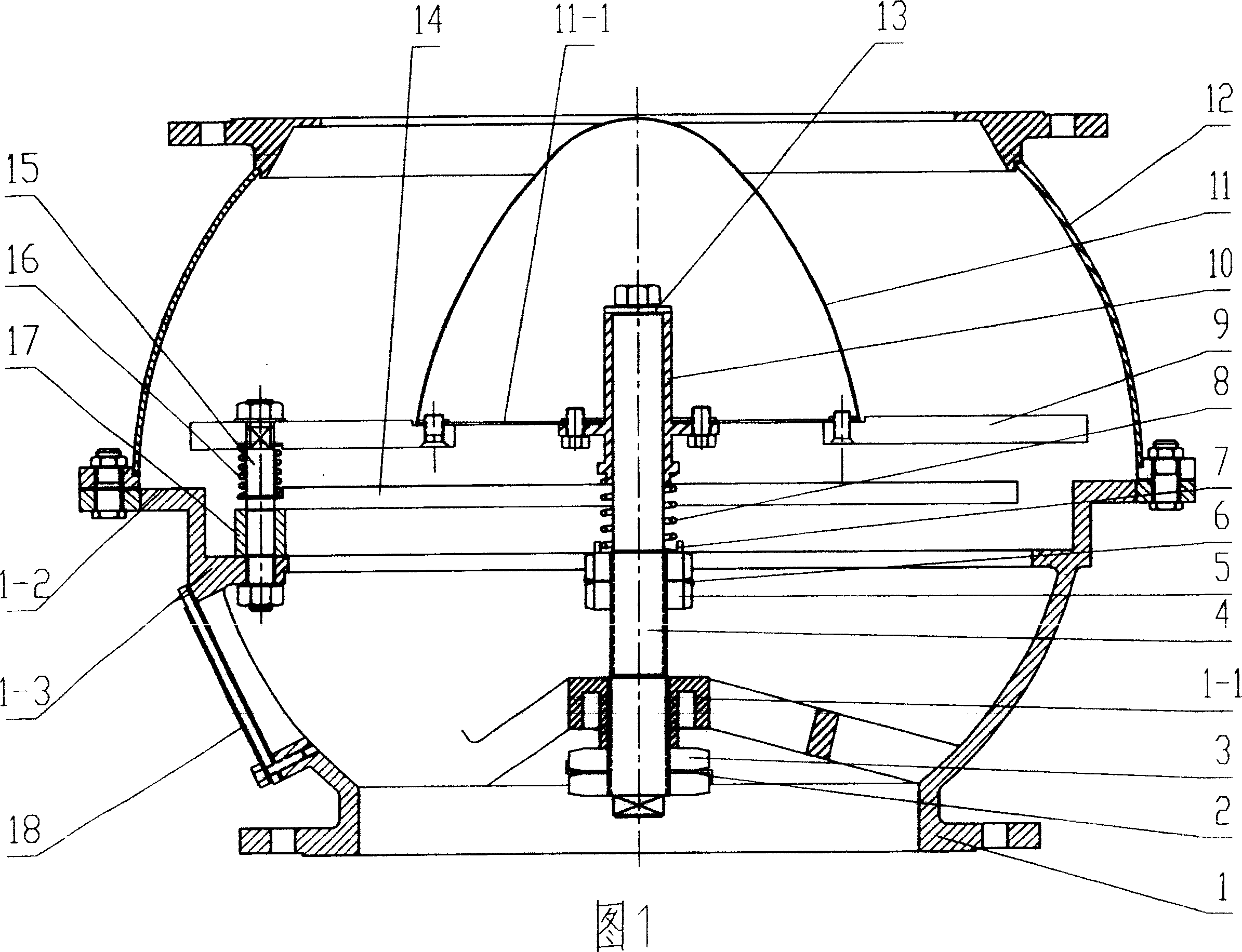
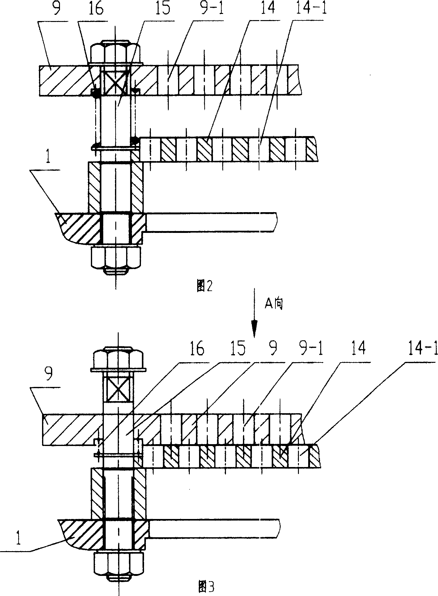
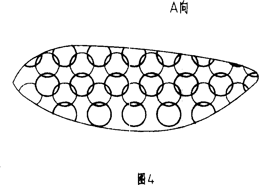
[0026] See the anti-explosion shock filter valve shown in Figures 1 to 4, including the front valve body 12, the rear valve body 1, the valve stem 4 and the valve plate 9, the cavities of the front valve body 12 and the rear valve body 1 are spherical, and both Made of metal material, the front valve body 12 and the rear valve body 1 are connected to the pipeline through their respective flanges, and the side of the rear valve body 1 has a window door 18 for easy adjustment. There is a valve seat 1-2 attached to the lower end surface of the valve plate 9 on the periphery of the rear valve body 1 front portion outside, and the valve stem 4 is connected on the support seat 1-1 of the rear valve body 1, and the valve seat 1-1 at the bottom of the support seat 1-1 The valve stem 4 is equipped with an adjusting piece that adjusts the distance between the valve plate 9 and the valve seat 1-2. The adjusting piece can use a commonly used nut 3, and lock the adjusted nut 3 through the l...


PUM


Abstract

An explosion-proof filtering valve has good instant characteristics and can filter a little gas to make it into the valve body so as to open the valve plate quickly. It consists of a front body, a rear one, a valve bar fixed on a support of a rear seat matched with a valve plate in the front body and on the outer periphery of the rear body, a regulating element equipped on the valve bar, a spherical cap, a sealing plate fixed on the cap to be sleeved on the valve bar and shifted in a radial way, a reset spring sleeved the valve bar and connected with the regulating element and the bottom of the cap seat, a buffer plate connected with the valve plate via a buffer spring, upper and lower buffer holes arranged uniformly on the valve plate with their central lines staged, partial through holes forming a secondary channel to filter when the valve plate and buffer plate are pressed together.

Description

technical field [0001] The invention relates to an anti-explosion valve, in particular to an anti-explosion shock filter valve which prevents the shock wave generated by the explosion from passing through the intake pipeline and can ventilate. Background technique [0002] The anti-explosion shock valve used in civil air defense projects, gas pipelines and other places is mainly composed of valve body, valve seat, valve plate, valve stem, etc. There is a main spring between the supporting seat of the valve plate and the valve stem. When the front of the pipeline or the front of the valve explodes due to various reasons, the high-speed and high-pressure shock wave generated by the explosion will pass through the front of the pipe. At this time, due to the sudden increase of the pressure at the front end of the valve plate, the pressure difference between the front and rear of the valve plate exceeds the elastic force of the main spring, the main spring is instantly compressed...

Claims


Application Information

Patent Timeline
Patent Type & Authority Patents(China)
IPC IPC(8): F16K17/00F16K47/00
Inventor 骆成汉
Owner 常州市汇丰船舶附件厂
Why Eureka
Try Eureka