Pulse-width modulation circuit and method

A pulse width modulation and pulse width modulation technology, which is applied to pulse modulation, devices and electrical components that perform computing operations by changing the amount of electricity or magnetism, and can solve problems such as pulse width modulation and improve sound quality. , multi-sampling rate, improve the effect of electromagnetic interference

Inactive Publication Date: 2007-04-11
SUNPLUS TECH CO LTD
View PDF6 Cites 0 Cited by
  • Summary
  • Abstract
  • Description
  • Claims
  • Application Information

AI Technical Summary

Problems solved by technology

In order to solve the defects of the existing pulse width modulation, relevant manufacturers have tried their best to find a solution, but no suitable design has been developed for a long time. This is obviously a problem that the relevant industry is eager to solve

Method used


Image

  • Pulse-width modulation circuit and method
  • Pulse-width modulation circuit and method
  • Pulse-width modulation circuit and method

Examples


Embodiment Construction

[0065] The specific structure, method steps, features and effects of the pulse width modulation circuit and method according to the present invention will be described in detail below with reference to the accompanying drawings and preferred embodiments.

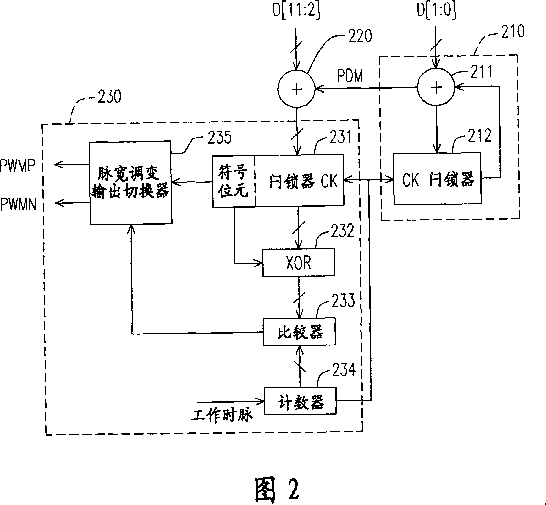
[0066] Please refer to FIG. 2 , which is a schematic block diagram of a PWM circuit according to a preferred embodiment of the present invention. The PWM circuit 200 is adapted to dithering the output pulse width in 2^N frames according to an input data having M+N bits. signal. Since the input data D[M:N] has positive and negative values, that is, the D[M] bit is a sign bit, the output pulse width modulation signal includes positive pulse width modulation signal PWMP and negative pulse width modulation Signal PWMN.

[0067] In Figure 2, M=10, N=2 is taken as an example, so if the input data D[11:0] is "00, 1000, 0000, 01", that is, the positive pulse width modulation signal PWMP that should be transmitted When the pulse w...


PUM


Abstract

N bits in input data are received by using pulse-numbers modulator. Pulse number of pulse-numbers modulation signal related to value of lower N bits in input data are output in 2N pieces of message frame. Using adder adds input data in higher M bits with value of pulse-numbers modulation signal output from pulse-numbers modulator generates a value of pulse width modulation. Based on value of pulse width modulation output from adder, using pulse width modulator outputs vibrated pulse width modulation signal in 2N pieces of message frame in order to raise tone quality of pulse width modulation and improve issue of electromagnetic interference.

Description

technical field [0001] The present invention relates to a pulse width modulation (Pulse Width Modulation, referred to as PWM) circuit and method, in particular to a pulse width modulation can improve the sound quality and reduce electromagnetic interference (Electro-magnetic Interference, referred to as EMI) Pulse width modulation circuit and method. Background technique [0002] In digital circuits for audio processing, pulse width modulation is the most commonly used modulation method. The so-called pulse width modulation is to refer to the cycle of a working clock representing the pulse width modulation service rate (PWM service rate) when outputting audio signals, so as to determine the value of the digital audio data (data) Adjust the pulse width of the output audio signal. [0003] Please refer to FIG. 1 , which is a schematic diagram of pulse width modulation of audio data with 10-bit resolution. In the figure, T1 is the period of the working clock representing the...

Claims


Application Information

Patent Timeline
IPC IPC(8): H03K7/00G06G7/161
Inventor 徐汉华
Owner SUNPLUS TECH CO LTD
Why Eureka
Try Eureka