
Image regulating method and image forming device

An image adjustment, image technique, applied to perform effective color matching adjustments. ,In the field of image forming devices, it can solve the problems of useless images, large distances, and concentrations that do not meet specific standards, so as to reduce the consumption of developer and the effect of not prolonging the adjustment time.

Inactive Publication Date: 2007-04-11
SHARP KK
View PDF6 Cites 0 Cited by
  • Summary
  • Abstract
  • Description
  • Claims
  • Application Information

AI Technical Summary

Problems solved by technology

[0007] However, in an image forming apparatus of a tandem system composed of a plurality of linearly arranged image forming units forming color component images, the distance between the image forming unit and the detector for detecting image adjustment is very large. A matching image is formed before checking the density, and when the detector detects the image for density control, the density does not reach a certain standard, and useless image formation is performed

Method used


Image

  • Image regulating method and image forming device
  • Image regulating method and image forming device
  • Image regulating method and image forming device

Examples


no. 1 example

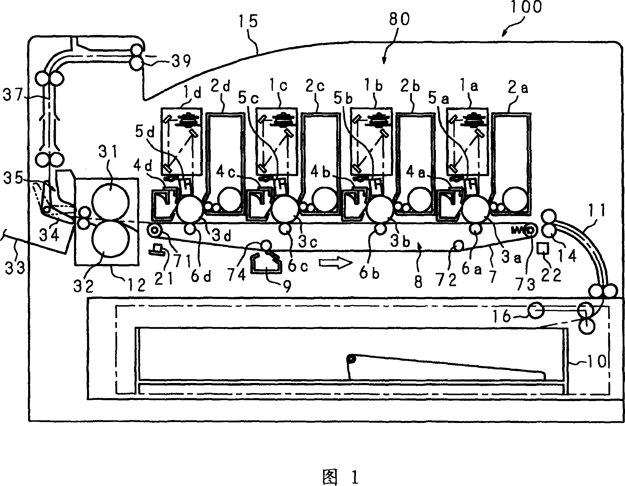
[0079] In the image forming apparatus 100 of the first embodiment, the toner images of the color components formed at the image forming station 80 are transferred to the transfer belt 7 at the time of color matching adjustment (registration adjustment). At this time, a reference toner image (hereinafter, referred to as a reference patch image) from a color component toner image is transferred to the transfer belt 7, and then, toners of other color components used for color misregistration adjustment An image (hereinafter, referred to as an adjustment block image) is transferred to this reference block image.

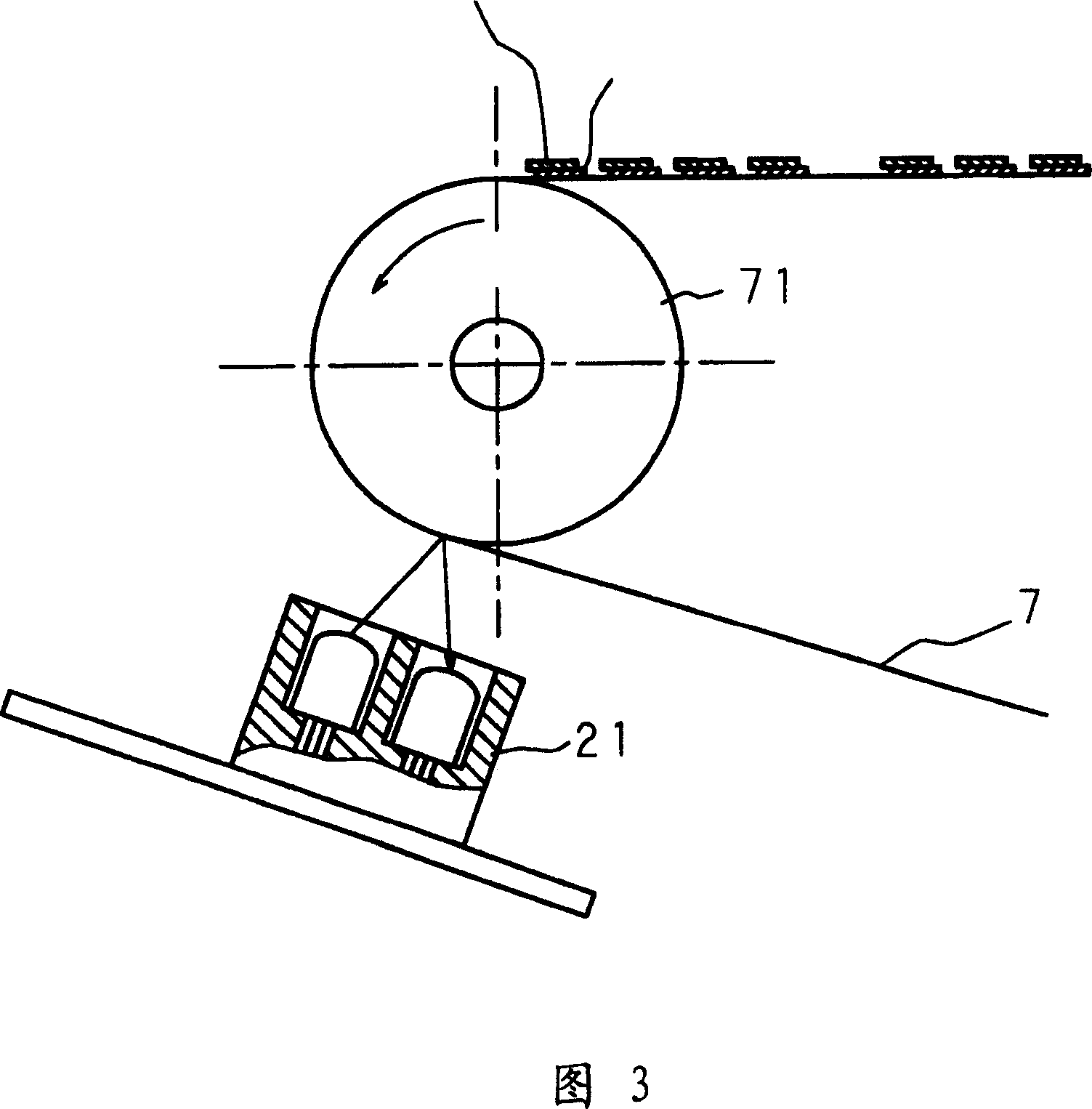
[0080] The transfer belt 7 is rotated and driven by the transfer belt driving roller 71. When the reference patch image K (black) and the adjustment patch image C (cyan) formed on the transfer belt 7 reach the overlap detection sensor 21 as shown in FIG. position, the overlap detection sensor 21 detects the density of the reference patch image and the adjustment patch im...

no. 2 example

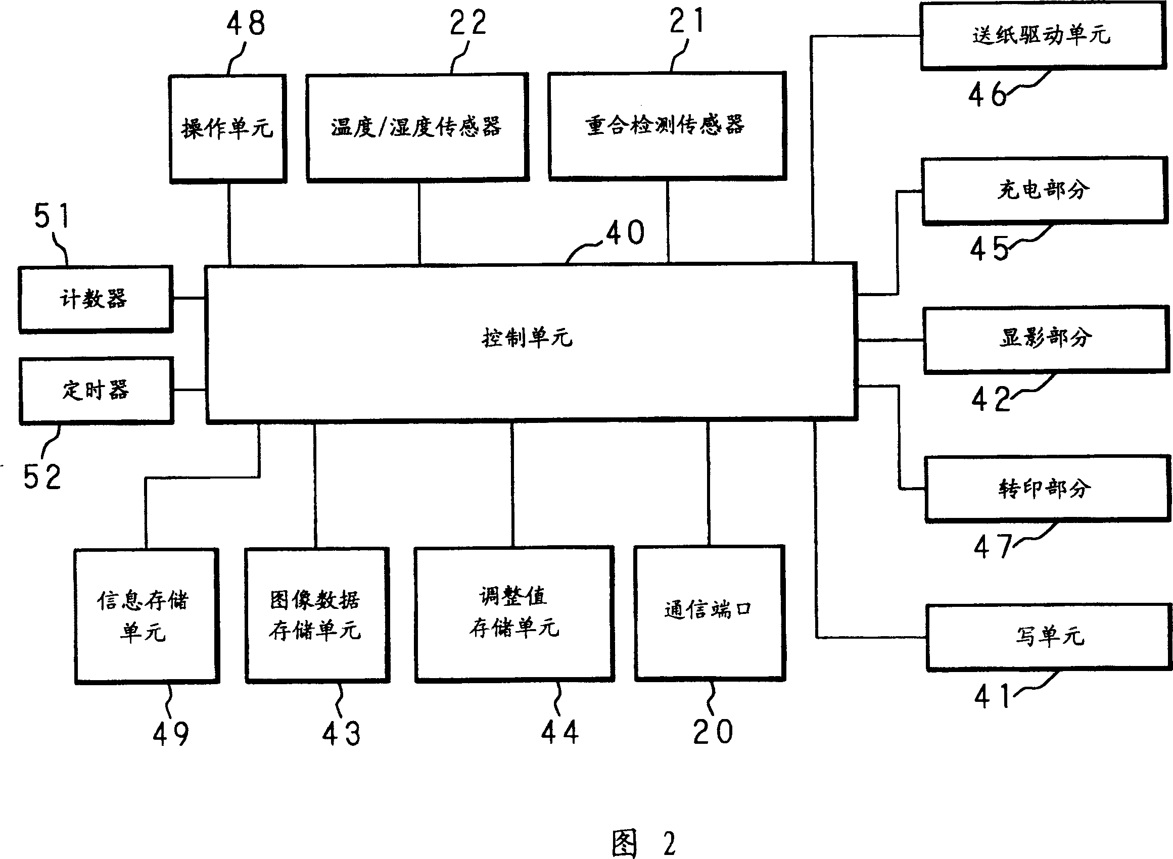
[0138] The image forming apparatus 100 in the second embodiment is designed to perform process control (adjustment process) for controlling image forming conditions, detection of image quality, and color matching adjustment by detecting the overlapping state of color component images.

[0139] In the process control, the formation is controlled based on the density of the patch image transferred on the transfer belt 7 (transfer carrier) by the photosensitive drum 3, and the environmental conditions (temperature and humidity) of an environmental sensor not shown in the figure. Better image, by changing, for example, the output or luminous time of the writing unit 41, the developing bias of the developing portion 42, the grid bias of the charging portion 45, the transfer bias of the transferring portion 47, the image processing unit (not shown) out) with a midtone table.

[0140] In the image quality inspection, the density of the image quality inspection image transferred on th...


PUM


Abstract

Images based on each of a plurality of color components are formed; the formed images are transferred on each transfer medium to form an image quality determining image; the image quality of the image quality determining image is determined on the basis of the detected density thereof, an adjustment image is formed by overlaying and transferring an image of other color component to be adjusted to the reference image of the reference color image out of the plurality of color components, on the transfer medium; the density of the adjustment image is detected; and the image forming position of the other color component to be adjusted is adjusted on the basis of the detected density. At the time of executing the color matching adjustment process for detecting the overlaid state of color component images, it is determined whether a specified time has passed or not since the previous adjustment process, a specified number of images are formed or not, environments are changed or not, and the power source is turned on or off or not. When it is predicted that the quality of the formed image is out of an appropriate range, a quality checking image is formed, its image quality is checked, and the color matching adjustment process is executed only when it is within an appropriate range.

Description

Background of the invention [0001] The present invention relates to an adjustment method of an image forming apparatus of an electrophotographic system, such as color matching adjustment, and an image forming apparatus, in particular, an image adjustment method and an image forming apparatus in which an image carrier ( Used to automatically adjust the color misregistration of a multi-color image when a multi-color image is formed from a color component image on an image forming device; photosensitive drum) or a transfer carrier (transfer medium: transfer belt, paper). Background technique [0002] An image forming apparatus, such as a digital color copier or a digital color printer, is designed to divide input data into a plurality of color components and process the image to form a multicolor image by overlapping each color component image. When forming a multi-color image, when each color component image is not properly overlapped, the multi-color image formed will have co...

Claims


Application Information

Patent Timeline
Patent Type & Authority Patents(China)
IPC IPC(8): G03G21/00G03G21/20G03G15/06H04N1/047H04N1/50
CPCH04N1/047H04N2201/0471H04N1/506H04N2201/04722H04N2201/04732
Inventor 高京介原田吉和冨田教夫元山贵晴真锅申生山中敏央
Owner SHARP KK
Learn More