Eureka AIR delivers breakthrough ideas for toughest innovation challenges, trusted by R&D personnel around the world.

Apparatus and method for treating a fluid

A technology for treating fluids and treatment areas, applied in chemical instruments and methods, spraying devices, spraying devices, etc., can solve problems such as increasing height and reducing maximum feed rate

Inactive Publication Date: 2007-03-28
SHELL INT RES MAATSCHAPPIJ BV
View PDF5 Cites 22 Cited by
  • Summary
  • Abstract
  • Description
  • Claims
  • Application Information

AI Technical Summary

Problems solved by technology

This vortex reduces the maximum feed rate and increases the height of the column necessary to achieve complete distillation

Method used


Image

  • Apparatus and method for treating a fluid
  • Apparatus and method for treating a fluid

Examples


Embodiment Construction

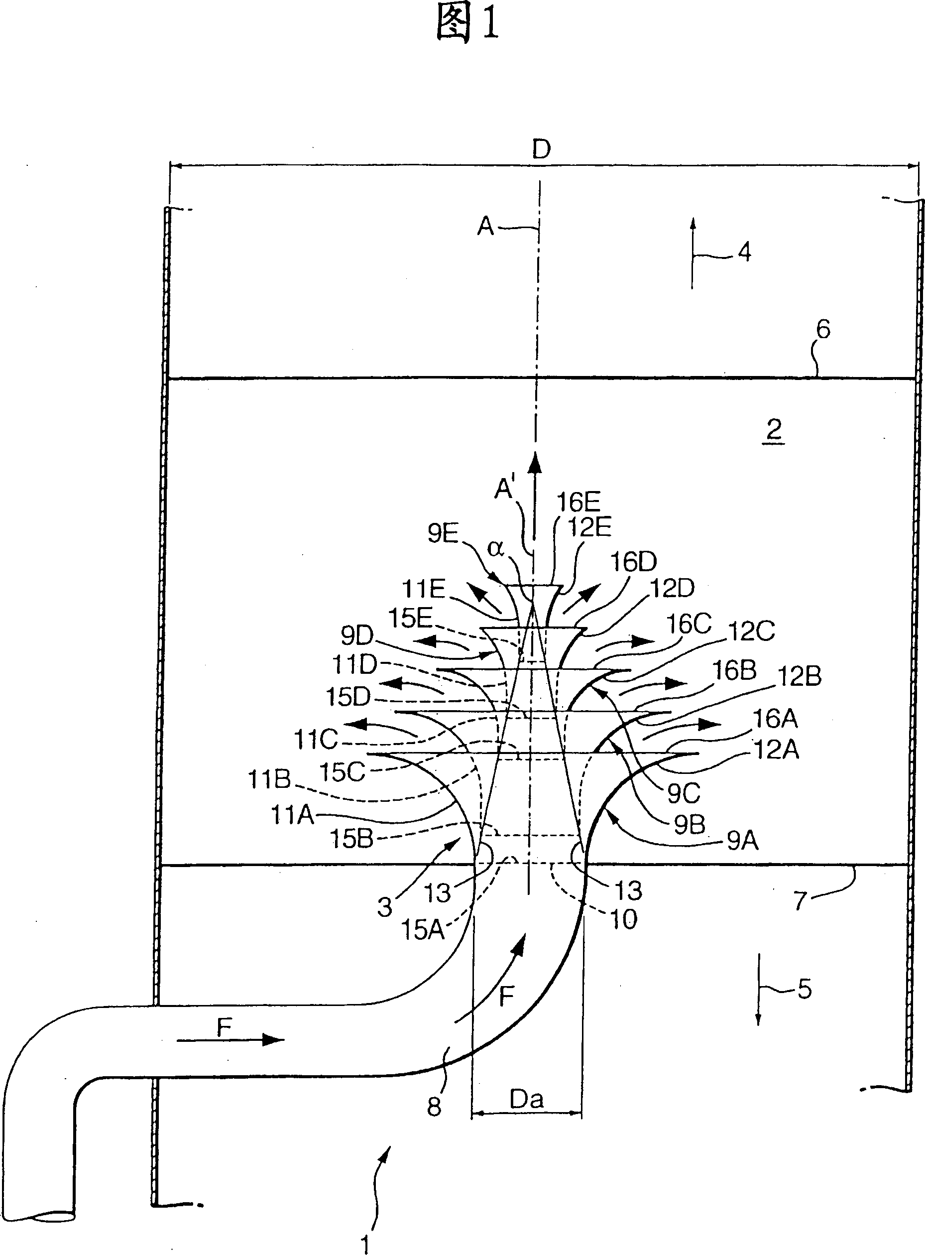
[0025] Referring to Figure 1, Figure 1 shows one section of a distillation column 1, which is typically used in a vertical orientation, as shown. The distillation column has a vertical longitudinal axis A and a substantially circular horizontal cross-section. The distillation column 1 comprises a first treatment zone 2 having an axis coincident with the axis A of the distillation column 1 and a fluid inlet arrangement 3 arranged in the treatment zone 2 . The first treatment zone 2 is arranged midway between the top and the bottom of the distillation tower 1. The top and bottom positions of the above-mentioned distillation tower 1 are represented by arrows 4 and 5 respectively, and the above-mentioned arrows 4 and 5 also represent passage through The corresponding upward gas flow and downward liquid flow of the above-mentioned distillation column.

[0026] The first treatment zone 2 is bounded in the direction of the top by a horizontally arranged gas treatment tray 6 and in t...


PUM


Abstract

An apparatus for treating a fluid, comprising at least one treating zone (2), and a fluid inlet (3) and separation device disposed therein for introducing a separated mixture of liquid and gas into the treating zone (2). The fluid inlet (3) device comprises a series of coaxially disposed circumferential vanes (9A-9E), wherein each circumferential vane curvedly extends between an intercepting part having a substantially axially directed leading edge and a deflecting part having a substantially radially outwardly extending trailing edge, and wherein the central axis (A') of the inlet device (3) extends parallel or coaxial with an upwardly extending axis of the treating zone (2). The invention further relates to a fluid inlet device (3), to a use of the fluid inlet device, and to a method for treating a fluid.

Description

technical field [0001] The invention relates to a device for treating fluids, said device comprising at least one treatment zone and a fluid inlet and separation device arranged therein for introducing a mixture of liquid and gas into the treatment in the district. Background technique [0002] In the chemical and petrochemical industries it is often the case that a mixture of liquids and vapors must be fed to a process zone, such as the inlet process zone of a vertical column with a plurality of adjacent process zones, wherein Gas and liquid are brought into countercurrent contact to exchange heat and matter. An example of such a column is a distillation column, eg a vacuum distillation column and small gas-liquid separators as described in EP-A-195464. [0003] In such a column, during normal operation, the liquid flows down from the top to the bottom, while the gas flows up from the bottom to the top. In the present description and claims the term "gas" is used to refe...

Claims


Application Information

Patent Timeline
Patent Type & Authority Patents(China)
IPC IPC(8): B01D3/00B05B1/26B01J19/26
CPCB01D3/008B01J19/26B01D3/00B05B1/26
Inventor 格雷厄姆·A·戴维斯约翰尼斯·L·努尔延雅拉尔·H·齐亚
Owner SHELL INT RES MAATSCHAPPIJ BV
Why Eureka
Eureka Blog
Learn More